SteelTension and bending

A W shape, HSS or channel under axial tension and strong-axis bending, CSA S16 Cl. 13.9. Check a W, WWF, S or HP shape, a rectangular HSS or a channel under a factored tension and a moment about its strong axis. The section is classified by S16 Table 2; the tension and moment are combined by Cl. 13.9 with the laterally supported moment resistance, and again, less the tension's relief, with the lateral-torsional buckling resistance over the unbraced length.

First report free, then a free sign-in

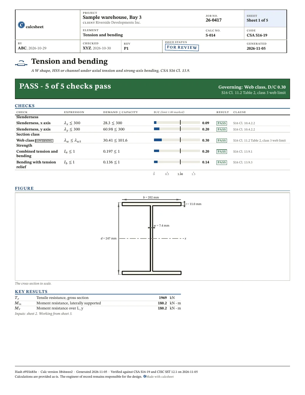
PASS Governing: Web class, D/C 0.30, S16 Cl. 11.2 Table 2, class 3 web limit5 of 5 checks below pass

Given

Jump to results

Type any value, everything below recomputes. Hover or tap a symbol to trace it.

Loads
changed from the declared value TfT_{f} kN\mathrm{kN} 0-50,000
changed from the declared value MfM_{f} kN⋅m\mathrm{kN} \cdot \mathrm{m} 0-10,000
changed from the declared value ω2\omega_{2} 1-2.5
Section
changed from the declared value
changed from the declared value FyF_{y} MPa\mathrm{MPa} 200-700
Bracing
changed from the declared value LxL_{x} mm\mathrm{mm} 100-30,000
changed from the declared value LyL_{y} mm\mathrm{mm} 100-30,000
d = 247 mm b = 202 mm t = 11.0 mm w = 7.4 mm x
The cross-section to scale.

Title block

Optional. Printed in the title block of the PDF.

Checks

! marks a check that passes with D/C at or above 0.95: close to its limit. The band is a site convention, not a code limit.

Slenderness

Check D/C Utilisation Result
Slenderness, x axisS16 Cl. 10.4.2.2λx≤300⇒28.3≤300\htmlClass{sym-lambda_x}{\lambda_{x}} \leq 300 \quad \Rightarrow \quad \htmlClass{sym-lambda_x}{28.3} \leq 300 0.09 PASS
Slenderness, y axisS16 Cl. 10.4.2.2λy≤300⇒60.98≤300\htmlClass{sym-lambda_y}{\lambda_{y}} \leq 300 \quad \Rightarrow \quad \htmlClass{sym-lambda_y}{60.98} \leq 300 0.20 PASS

Section class

Check D/C Utilisation Result
Web classS16 Cl. 11.2 Table 2, class 3 web limitλw≤λw3⇒30.41≤101.6\htmlClass{sym-lambda_w}{\lambda_{w}} \leq \htmlClass{sym-lambda_w3}{\lambda_{w3}} \quad \Rightarrow \quad \htmlClass{sym-lambda_w}{30.41} \leq \htmlClass{sym-lambda_w3}{101.6} 0.30 PASS

Strength

Check D/C Utilisation Result
Combined tension and bendingS16 Cl. 13.9.1Ia≤1⇒0.197≤1\htmlClass{sym-I_a}{I_{a}} \leq 1 \quad \Rightarrow \quad \htmlClass{sym-I_a}{0.197} \leq 1 0.20 PASS
Bending with tension reliefS16 Cl. 13.9.3Ib≤1⇒0.136≤1\htmlClass{sym-I_b}{I_{b}} \leq 1 \quad \Rightarrow \quad \htmlClass{sym-I_b}{0.136} \leq 1 0.14 PASS

Results

Quantity Description Value Unit
Tr\htmlClass{sym-T_r}{T_{r}} Tensile resistance, gross section 1969 kN\mathrm{kN}
Mrx\htmlClass{sym-M_rx}{M_{\mathrm{rx}}} Moment resistance, laterally supported 180.2 kN⋅m\mathrm{kN} \cdot \mathrm{m}
Mr\htmlClass{sym-M_r}{M_{r}} Moment resistance over L_y 180.2 kN⋅m\mathrm{kN} \cdot \mathrm{m}
Also worth checking
  • Bending about the minor axis: Cl. 13.9.1 and 13.9.3 are taken with M_fy = 0
  • Cl. 13.9.2, the 0.85 M_fx form for class 1 and 2 I-shapes, which also requires M_fx/M_r <= 1 with M_r from Cl. 13.6 and no tension relief; the calc takes Cl. 13.9.1 and 13.9.3 as the governing reading, with 13.9.2 an alternative to them
  • T_r is the gross section's yield, Cl. 13.2 a) i), only: net section fracture, Cl. 13.2 a) iii) and Cl. 12, and block shear, Cl. 13.2 a) ii) and Cl. 13.11, are not checked
  • Load applied above the shear centre, Cl. 13.6.1 a): M_u is for load at the shear centre, with omega_2 as entered
  • Cantilevers, Cl. 13.6.1 d): L_y is taken as the length of a segment between effective brace points
  • The strength and stiffness of the lateral bracing and the twist restraint at the supports, Cl. 9.3 and 9.4
  • Torsion of a channel loaded off its shear centre, Cl. 9.9
  • A load that reverses to compression, which needs Cl. 13.8
  • Shear, deflection, the connections and local effects at the load points
  • Class 4 webs, which fail the web class check, and class 4 channel flanges, which fail the flange class check

Derivation

S.1 Resistance factor

Compared with CSA S16-19 Cl. 13.1 a) (phi = 0.90, structural steel)

ϕ=0.9(Resistance factor | S16 Cl. 13.1)\begin{aligned} \htmlClass{sym-phi}{\phi} &= 0.9 \quad \left(\text{Resistance factor | S16 Cl. 13.1}\right) \end{aligned}
S.2 Steel modulus

Compared with CSA S16-19 Cl. 3.2 (E = 200 000 MPa assumed)

E=200000 MPa\begin{aligned} \htmlClass{sym-E}{E} &= 200000\ \mathrm{MPa} \end{aligned}
S.3 Shear modulus

Compared with CSA S16-19 Cl. 3.2 (G = 77 000 MPa assumed)

G=77000 MPa\begin{aligned} \htmlClass{sym-G}{G} &= 77000\ \mathrm{MPa} \end{aligned}
S.4 Root of the yield strength

Accepted by the author: definition, the root of F_y in MPa that every CSA S16-19 Table 2 limit divides by

rootF,y=Fy1 MPa=350 MPa1 MPa=18.71\begin{aligned} \htmlClass{sym-root_F_y}{\mathrm{root}_{F,y}} &= \sqrt{\frac{\htmlClass{sym-F_y}{F_{y}}}{1\ \mathrm{MPa}}} \\ &= \sqrt{\frac{\htmlClass{sym-F_y}{350\ \mathrm{MPa}}}{1\ \mathrm{MPa}}} \\ &= 18.71 \end{aligned}
S.5 Gross area

Accepted by the author: CISC SST 12.1 section table value (sections-data/cisc_12.1/), a given and not a formula; an HSS wall is the table's design thickness Tdes; W250x49 A_Th

A0=6250 mm2(Cross-sectional area)\begin{aligned} \htmlClass{sym-A_0}{A_{0}} &= 6250\ \mathrm{mm}^{2} \quad \left(\text{Cross-sectional area}\right) \end{aligned}
S.6 Radius of gyration about x

Accepted by the author: CISC SST 12.1 section table value (sections-data/cisc_12.1/), a given and not a formula; an HSS wall is the table's design thickness Tdes; W250x49 Rx

rx=106 mm(Radius of gyration about axis XX)\begin{aligned} \htmlClass{sym-r_x}{r_{x}} &= 106\ \mathrm{mm} \quad \left(\text{Radius of gyration about axis XX}\right) \end{aligned}
S.7 Radius of gyration about y

Accepted by the author: CISC SST 12.1 section table value (sections-data/cisc_12.1/), a given and not a formula; an HSS wall is the table's design thickness Tdes; W250x49 Ry

ry=49.2 mm(Radius of gyration about axis YY)\begin{aligned} \htmlClass{sym-r_y}{r_{y}} &= 49.2\ \mathrm{mm} \quad \left(\text{Radius of gyration about axis YY}\right) \end{aligned}
S.8 Slenderness ratio about x

Compared with CSA S16-19 Cl. 10.4.1 (the slenderness ratio of a member in tension is the unbraced length L over the radius of gyration, no K)

S16 Cl. 10.4.1, a tension member takes L/r with no K

λx=Lxrx=3000 mm106 mm=28.3\begin{aligned} \htmlClass{sym-lambda_x}{\lambda_{x}} &= \frac{\htmlClass{sym-L_x}{L_{x}}}{\htmlClass{sym-r_x}{r_{x}}} \\ &= \frac{\htmlClass{sym-L_x}{3000\ \mathrm{mm}}}{\htmlClass{sym-r_x}{106\ \mathrm{mm}}} \\ &= 28.3 \end{aligned}
S.9 Slenderness ratio about y

Compared with CSA S16-19 Cl. 10.4.1 (the slenderness ratio of a member in tension is the unbraced length L over the radius of gyration, no K)

S16 Cl. 10.4.1, a tension member takes L/r with no K

λy=Lyry=3000 mm49.2 mm=60.98\begin{aligned} \htmlClass{sym-lambda_y}{\lambda_{y}} &= \frac{\htmlClass{sym-L_y}{L_{y}}}{\htmlClass{sym-r_y}{r_{y}}} \\ &= \frac{\htmlClass{sym-L_y}{3000\ \mathrm{mm}}}{\htmlClass{sym-r_y}{49.2\ \mathrm{mm}}} \\ &= 60.98 \end{aligned}
S.10 Tensile resistance

Compared with CSA S16-19 Cl. 13.2 a) i) (T_r = phi A_g F_y, phi = 0.90 per Cl. 13.1 a); A_0 is the gross area)

S16 Cl. 13.2, gross section yield

Tr=ϕ⋅A0⋅Fy=0.9⋅6250 mm2⋅350 MPa=1969 kN\begin{aligned} \htmlClass{sym-T_r}{T_{r}} &= \htmlClass{sym-phi}{\phi} \cdot \htmlClass{sym-A_0}{A_{0}} \cdot \htmlClass{sym-F_y}{F_{y}} \\ &= \htmlClass{sym-phi}{0.9} \cdot \htmlClass{sym-A_0}{6250\ \mathrm{mm}^{2}} \cdot \htmlClass{sym-F_y}{350\ \mathrm{MPa}} \\ &= 1969\ \mathrm{kN} \end{aligned}
S.11 Flange width

Accepted by the author: CISC SST 12.1 section table value (sections-data/cisc_12.1/), a given and not a formula; an HSS wall is the table's design thickness Tdes; W250x49 B

b=202 mm(Width of flange or horizontal leg)\begin{aligned} \htmlClass{sym-b}{b} &= 202\ \mathrm{mm} \quad \left(\text{Width of flange or horizontal leg}\right) \end{aligned}
S.12 Depth

Accepted by the author: CISC SST 12.1 section table value (sections-data/cisc_12.1/), a given and not a formula; an HSS wall is the table's design thickness Tdes; W250x49 D

d=247 mm(Depth of section or height of vertical leg)\begin{aligned} \htmlClass{sym-d}{d} &= 247\ \mathrm{mm} \quad \left(\text{Depth of section or height of vertical leg}\right) \end{aligned}
S.13 Flange or wall thickness

Accepted by the author: CISC SST 12.1 section table value (sections-data/cisc_12.1/), a given and not a formula; an HSS wall is the table's design thickness Tdes; W250x49 T

t=11 mm(Thickness of flange)\begin{aligned} \htmlClass{sym-t}{t} &= 11\ \mathrm{mm} \quad \left(\text{Thickness of flange}\right) \end{aligned}
S.14 Web or wall thickness

Accepted by the author: CISC SST 12.1 section table value (sections-data/cisc_12.1/), a given and not a formula; an HSS wall is the table's design thickness Tdes; W250x49 W

w=7.4 mm(Thickness of web)\begin{aligned} \htmlClass{sym-w}{w} &= 7.4\ \mathrm{mm} \quad \left(\text{Thickness of web}\right) \end{aligned}
S.15 Flange outstand

Compared with CSA S16-19 Cl. 11.3.1 c) (outstand of a beam flange is one-half of the full nominal flange width, b_out = b/2)

bout=b2=202 mm2=101 mm\begin{aligned} \htmlClass{sym-b_out}{b_{\mathrm{out}}} &= \frac{\htmlClass{sym-b}{b}}{2} \\ &= \frac{\htmlClass{sym-b}{202\ \mathrm{mm}}}{2} \\ &= 101\ \mathrm{mm} \end{aligned}
S.16 Flange width-to-thickness ratio

Accepted by the author: definition, the flange outstand over its thickness b_out/t that Table 2 limits (b_out is the S16 Cl. 11.3.1 c) half flange, its own row)

λf=boutt=101 mm11 mm=9.182\begin{aligned} \htmlClass{sym-lambda_f}{\lambda_{f}} &= \frac{\htmlClass{sym-b_out}{b_{\mathrm{out}}}}{\htmlClass{sym-t}{t}} \\ &= \frac{\htmlClass{sym-b_out}{101\ \mathrm{mm}}}{\htmlClass{sym-t}{11\ \mathrm{mm}}} \\ &= 9.182 \end{aligned}
S.17 Class 1 limit, flange

Compared with CSA S16-19 Table 2 (flanges of I-sections in flexure: b_el/t not over 145/sqrt(F_y) for Class 1; table extraction is garbled but the 145, 170, 200 limits are present)

S16 Table 2, flanges

λf1=145rootF,y=14518.71=7.751\begin{aligned} \htmlClass{sym-lambda_f1}{\lambda_{f1}} &= \frac{145}{\htmlClass{sym-root_F_y}{\mathrm{root}_{F,y}}} \\ &= \frac{145}{\htmlClass{sym-root_F_y}{18.71}} \\ &= 7.751 \end{aligned}
S.18 Class 2 limit, flange

Compared with CSA S16-19 Table 2 (flanges of I-sections in flexure: b_el/t not over 170/sqrt(F_y) for Class 2; table extraction is garbled but the 145, 170, 200 limits are present)

S16 Table 2, flanges

λf2=170rootF,y=17018.71=9.087\begin{aligned} \htmlClass{sym-lambda_f2}{\lambda_{f2}} &= \frac{170}{\htmlClass{sym-root_F_y}{\mathrm{root}_{F,y}}} \\ &= \frac{170}{\htmlClass{sym-root_F_y}{18.71}} \\ &= 9.087 \end{aligned}
S.19 Class 3 limit, flange

Compared with CSA S16-19 Table 2 (flanges of I-sections in flexure: b_el/t not over 200/sqrt(F_y) for Class 3; table extraction is garbled but the 145, 170, 200 limits are present)

S16 Table 2, flanges

λf3=200rootF,y=20018.71=10.69\begin{aligned} \htmlClass{sym-lambda_f3}{\lambda_{f3}} &= \frac{200}{\htmlClass{sym-root_F_y}{\mathrm{root}_{F,y}}} \\ &= \frac{200}{\htmlClass{sym-root_F_y}{18.71}} \\ &= 10.69 \end{aligned}
S.20 Web depth-to-thickness ratio

Compared with CSA S16-19 Cl. 11.3.2 d) (web of a hot-rolled section, h = clear distance between flanges, so h/w = (d - 2t)/w)

λw=d−2⋅tw=247 mm−2⋅11 mm7.4 mm=30.41\begin{aligned} \htmlClass{sym-lambda_w}{\lambda_{w}} &= \frac{\htmlClass{sym-d}{d} - 2 \cdot \htmlClass{sym-t}{t}}{\htmlClass{sym-w}{w}} \\ &= \frac{\htmlClass{sym-d}{247\ \mathrm{mm}} - 2 \cdot \htmlClass{sym-t}{11\ \mathrm{mm}}}{\htmlClass{sym-w}{7.4\ \mathrm{mm}}} \\ &= 30.41 \end{aligned}
S.21 Class 1 limit, web

Compared with CSA S16-19 Table 2 (webs of I-sections in flexure: h/w not over 1100/sqrt(F_y) for Class 1)

S16 Table 2, webs in flexure

λw1=1100rootF,y=110018.71=58.8\begin{aligned} \htmlClass{sym-lambda_w1}{\lambda_{w1}} &= \frac{1100}{\htmlClass{sym-root_F_y}{\mathrm{root}_{F,y}}} \\ &= \frac{1100}{\htmlClass{sym-root_F_y}{18.71}} \\ &= 58.8 \end{aligned}
S.22 Class 2 limit, web

Compared with CSA S16-19 Table 2 (webs of I-sections in flexure: h/w not over 1700/sqrt(F_y) for Class 2)

S16 Table 2, webs in flexure

λw2=1700rootF,y=170018.71=90.87\begin{aligned} \htmlClass{sym-lambda_w2}{\lambda_{w2}} &= \frac{1700}{\htmlClass{sym-root_F_y}{\mathrm{root}_{F,y}}} \\ &= \frac{1700}{\htmlClass{sym-root_F_y}{18.71}} \\ &= 90.87 \end{aligned}
S.23 Class 3 limit, web

Compared with CSA S16-19 Table 2 (webs of I-sections in flexure: h/w not over 1900/sqrt(F_y) for Class 3)

S16 Table 2, webs in flexure

λw3=1900rootF,y=190018.71=101.6\begin{aligned} \htmlClass{sym-lambda_w3}{\lambda_{w3}} &= \frac{1900}{\htmlClass{sym-root_F_y}{\mathrm{root}_{F,y}}} \\ &= \frac{1900}{\htmlClass{sym-root_F_y}{18.71}} \\ &= 101.6 \end{aligned}

Branch: λf≤λf1\lambda_{f} \leq \lambda_{f1} did not hold

Branch: λf≤λf2\lambda_{f} \leq \lambda_{f2} did not hold

Branch: λf≤λf3\lambda_{f} \leq \lambda_{f3} held

S.24 Flange class

Compared with CSA S16-19 Cl. 11.2 Table 2 (flange of an I-section in major-axis bending is Class 3 where 170/sqrt(F_y) < b_el/t <= 200/sqrt(F_y); W250x49 at 350 MPa 9.18 against 9.09 and 10.69)

classf=3(Flange class 3)\begin{aligned} \htmlClass{sym-class_f}{\mathrm{class}_{f}} &= 3 \quad \left(\text{Flange class 3}\right) \end{aligned}

Branch: λw≤λw1\lambda_{w} \leq \lambda_{w1} held

S.25 Web class

Compared with CSA S16-19 Cl. 11.2 Table 2 (I-section web with C_f = 0 is Class 1 where h/w <= 1100/sqrt(F_y); W250x49 at 350 MPa 30.4 against 58.8)

classw=1(Web class 1)\begin{aligned} \htmlClass{sym-class_w}{\mathrm{class}_{w}} &= 1 \quad \left(\text{Web class 1}\right) \end{aligned}
S.26 Section class

Accepted by the author: definition, the section takes the less favourable (higher numbered) of the flange and web classes, max(class_f, class_w)

sectionclass=max⁡(classf,classw)=max⁡(3,1)=3\begin{aligned} \htmlClass{sym-section_class}{\mathrm{section}_{\mathrm{class}}} &= \max\left(\htmlClass{sym-class_f}{\mathrm{class}_{f}}, \htmlClass{sym-class_w}{\mathrm{class}_{w}}\right) \\ &= \max\left(\htmlClass{sym-class_f}{3}, \htmlClass{sym-class_w}{1}\right) \\ &= 3 \end{aligned}

Branch: sectionclass≤2\mathrm{section}_{\mathrm{class}} \leq 2 did not hold

Branch: classf≤3\mathrm{class}_{f} \leq 3 held

S.27 Section modulus used

Accepted by the author: tabulated section modulus S_x of the designated section from the CISC tables, the class 3 modulus that Cl. 13.5 b) takes

S16 Cl. 13.5 (b), S for class 3

Ze=572000 mm3(Elastic section modulus about axis XX)\begin{aligned} \htmlClass{sym-Z_e}{Z_{e}} &= 572000\ \mathrm{mm}^{3} \quad \left(\text{Elastic section modulus about axis XX}\right) \end{aligned}
S.28 Moment at the modulus used, Z F_y, S F_y or S_e F_y

Accepted by the author: Statics: M = Z_e F_y, the fully plastic moment for Z or the first-yield moment for S (stress times modulus)

Mp=Ze⋅Fy=572000 mm3⋅350 MPa=200.2 kN⋅m\begin{aligned} \htmlClass{sym-M_p}{M_{p}} &= \htmlClass{sym-Z_e}{Z_{e}} \cdot \htmlClass{sym-F_y}{F_{y}} \\ &= \htmlClass{sym-Z_e}{572000\ \mathrm{mm}^{3}} \cdot \htmlClass{sym-F_y}{350\ \mathrm{MPa}} \\ &= 200.2\ \mathrm{kN} \cdot \mathrm{m} \end{aligned}
S.29 Moment resistance, laterally supported

Compared with CSA S16-19 Cl. 13.5 a) and b) (M_r = phi Z F_y for Class 1 and 2, phi S F_y for Class 3; Z_e carries the class's modulus)

S16 Cl. 13.5

Mrx=ϕ⋅Mp=0.9⋅200.2 kN⋅m=180.2 kN⋅m\begin{aligned} \htmlClass{sym-M_rx}{M_{\mathrm{rx}}} &= \htmlClass{sym-phi}{\phi} \cdot \htmlClass{sym-M_p}{M_{p}} \\ &= \htmlClass{sym-phi}{0.9} \cdot \htmlClass{sym-M_p}{200.2\ \mathrm{kN} \cdot \mathrm{m}} \\ &= 180.2\ \mathrm{kN} \cdot \mathrm{m} \end{aligned}
S.30 Moment of inertia about y

Accepted by the author: CISC SST 12.1 section table value (sections-data/cisc_12.1/), a given and not a formula; an HSS wall is the table's design thickness Tdes; W250x49 Iy

Iy=1.51×107 mm4(Moment of inertia about axis YY)\begin{aligned} \htmlClass{sym-I_y}{I_{y}} &= 1.51 \times 10^{7}\ \mathrm{mm}^{4} \quad \left(\text{Moment of inertia about axis YY}\right) \end{aligned}
S.31 Torsional constant

Accepted by the author: CISC SST 12.1 section table value (sections-data/cisc_12.1/), a given and not a formula; an HSS wall is the table's design thickness Tdes; W250x49 J

J=241000 mm4(St-Venant torsional constant)\begin{aligned} \htmlClass{sym-J}{J} &= 241000\ \mathrm{mm}^{4} \quad \left(\text{St-Venant torsional constant}\right) \end{aligned}
S.32 Warping constant

Accepted by the author: CISC SST 12.1 section table value (sections-data/cisc_12.1/), a given and not a formula; an HSS wall is the table's design thickness Tdes; W250x49 Cw

Cw=2.11×1011 mm6(Warping constant)\begin{aligned} \htmlClass{sym-C_w}{C_{w}} &= 2.11 \times 10^{11}\ \mathrm{mm}^{6} \quad \left(\text{Warping constant}\right) \end{aligned}
S.33 Critical elastic moment

Compared with CSA S16-19 Cl. 13.6.1 a) ii) (M_u = omega_2 pi/L sqrt(E I_y G J + (pi E/L)^2 I_y C_w), L = L_y; pi E = 628.3 GPa)

S16 Cl. 13.6

Mu=ω2⋅πLy⋅E⋅Iy⋅G⋅J+(628319 MPaLy)2⋅Iy⋅Cw=1⋅π3000 mm⋅200000 MPa⋅1.51×107 mm4⋅77000 MPa⋅241000 mm4+(628319 MPa3000 mm)2⋅1.51×107 mm4⋅2.11×1011 mm6=463.4 kN⋅m\begin{aligned} \htmlClass{sym-M_u}{M_{u}} &= \frac{\htmlClass{sym-omega_2}{\omega_{2}} \cdot \pi}{\htmlClass{sym-L_y}{L_{y}}} \cdot \sqrt{\htmlClass{sym-E}{E} \cdot \htmlClass{sym-I_y}{I_{y}} \cdot \htmlClass{sym-G}{G} \cdot \htmlClass{sym-J}{J} + \left(\frac{628319\ \mathrm{MPa}}{\htmlClass{sym-L_y}{L_{y}}}\right)^{2} \cdot \htmlClass{sym-I_y}{I_{y}} \cdot \htmlClass{sym-C_w}{C_{w}}} \\ &= \frac{\htmlClass{sym-omega_2}{1} \cdot \pi}{\htmlClass{sym-L_y}{3000\ \mathrm{mm}}} \cdot \sqrt{\htmlClass{sym-E}{200000\ \mathrm{MPa}} \cdot \htmlClass{sym-I_y}{1.51 \times 10^{7}\ \mathrm{mm}^{4}} \cdot \htmlClass{sym-G}{77000\ \mathrm{MPa}} \cdot \htmlClass{sym-J}{241000\ \mathrm{mm}^{4}} + \left(\frac{628319\ \mathrm{MPa}}{\htmlClass{sym-L_y}{3000\ \mathrm{mm}}}\right)^{2} \cdot \htmlClass{sym-I_y}{1.51 \times 10^{7}\ \mathrm{mm}^{4}} \cdot \htmlClass{sym-C_w}{2.11 \times 10^{11}\ \mathrm{mm}^{6}}} \\ &= 463.4\ \mathrm{kN} \cdot \mathrm{m} \end{aligned}

Branch: Mu>0.67⋅MpM_{u} > 0.67 \cdot M_{p} held

S.34 Moment resistance, laterally unsupported

Compared with CSA S16-19 Cl. 13.6.1 a) i) and b) i) (1.15 phi M (1 - 0.28 M/M_u) not over phi M, M = Z_e F_y: M_p for Class 1 and 2, M_y for Class 3; Class 4 basis differs, see report)

S16 Cl. 13.6.1 a) or b)

Mr=min⁡(1.15⋅ϕ⋅Mp⋅(1−0.28⋅MpMu),ϕ⋅Mp)=min⁡(1.15⋅0.9⋅200.2 kN⋅m⋅(1−0.28⋅200.2 kN⋅m463.4 kN⋅m),0.9⋅200.2 kN⋅m)=180.2 kN⋅m\begin{aligned} \htmlClass{sym-M_r}{M_{r}} &= \min\left(1.15 \cdot \htmlClass{sym-phi}{\phi} \cdot \htmlClass{sym-M_p}{M_{p}} \cdot \left(1 - \frac{0.28 \cdot \htmlClass{sym-M_p}{M_{p}}}{\htmlClass{sym-M_u}{M_{u}}}\right), \htmlClass{sym-phi}{\phi} \cdot \htmlClass{sym-M_p}{M_{p}}\right) \\ &= \min\left(1.15 \cdot \htmlClass{sym-phi}{0.9} \cdot \htmlClass{sym-M_p}{200.2\ \mathrm{kN} \cdot \mathrm{m}} \cdot \left(1 - \frac{0.28 \cdot \htmlClass{sym-M_p}{200.2\ \mathrm{kN} \cdot \mathrm{m}}}{\htmlClass{sym-M_u}{463.4\ \mathrm{kN} \cdot \mathrm{m}}}\right), \htmlClass{sym-phi}{0.9} \cdot \htmlClass{sym-M_p}{200.2\ \mathrm{kN} \cdot \mathrm{m}}\right) \\ &= 180.2\ \mathrm{kN} \cdot \mathrm{m} \end{aligned}
S.35 Tension and bending interaction

Compared with CSA S16-19 Cl. 13.9.1 (T_f/T_r + M_fx/M_rx + M_fy/M_ry not over 1.0, with M_fy = 0; M_rx per Cl. 13.5)

S16 Cl. 13.9.1

Ia=TfTr+MfMrx=60 kN1969 kN+30 kN⋅m180.2 kN⋅m=0.197\begin{aligned} \htmlClass{sym-I_a}{I_{a}} &= \frac{\htmlClass{sym-T_f}{T_{f}}}{\htmlClass{sym-T_r}{T_{r}}} + \frac{\htmlClass{sym-M_f}{M_{f}}}{\htmlClass{sym-M_rx}{M_{\mathrm{rx}}}} \\ &= \frac{\htmlClass{sym-T_f}{60\ \mathrm{kN}}}{\htmlClass{sym-T_r}{1969\ \mathrm{kN}}} + \frac{\htmlClass{sym-M_f}{30\ \mathrm{kN} \cdot \mathrm{m}}}{\htmlClass{sym-M_rx}{180.2\ \mathrm{kN} \cdot \mathrm{m}}} \\ &= 0.197 \end{aligned}
S.36 Bending less tension interaction

Compared with CSA S16-19 Cl. 13.9.3 a) and b) (M_fx/M_rx - T_f Z_x/(M_r A) for Class 1 and 2, S_x for Class 3; M_fy = 0, M_r per Cl. 13.6.1; a Class 4 I-shape or HSS takes the effective S_e where b) says S_x, conservative, see report)

S16 Cl. 13.9.3 a) and b)

Ib=MfMr−Tf⋅ZeMr⋅A0=30 kN⋅m180.2 kN⋅m−60 kN⋅572000 mm3180.2 kN⋅m⋅6250 mm2=0.136\begin{aligned} \htmlClass{sym-I_b}{I_{b}} &= \frac{\htmlClass{sym-M_f}{M_{f}}}{\htmlClass{sym-M_r}{M_{r}}} - \frac{\htmlClass{sym-T_f}{T_{f}} \cdot \htmlClass{sym-Z_e}{Z_{e}}}{\htmlClass{sym-M_r}{M_{r}} \cdot \htmlClass{sym-A_0}{A_{0}}} \\ &= \frac{\htmlClass{sym-M_f}{30\ \mathrm{kN} \cdot \mathrm{m}}}{\htmlClass{sym-M_r}{180.2\ \mathrm{kN} \cdot \mathrm{m}}} - \frac{\htmlClass{sym-T_f}{60\ \mathrm{kN}} \cdot \htmlClass{sym-Z_e}{572000\ \mathrm{mm}^{3}}}{\htmlClass{sym-M_r}{180.2\ \mathrm{kN} \cdot \mathrm{m}} \cdot \htmlClass{sym-A_0}{6250\ \mathrm{mm}^{2}}} \\ &= 0.136 \end{aligned}

Report

Sheet 1 and the first sheet of the working of the PDF report, at the declared values with a sample title block. First report free, then a free sign-in.
Show the two sheets
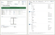
Sheet 1 of the Tension and bending report: title block, verdict, checks and figures
Sheet 1: title block, verdict, checks, figures · full size
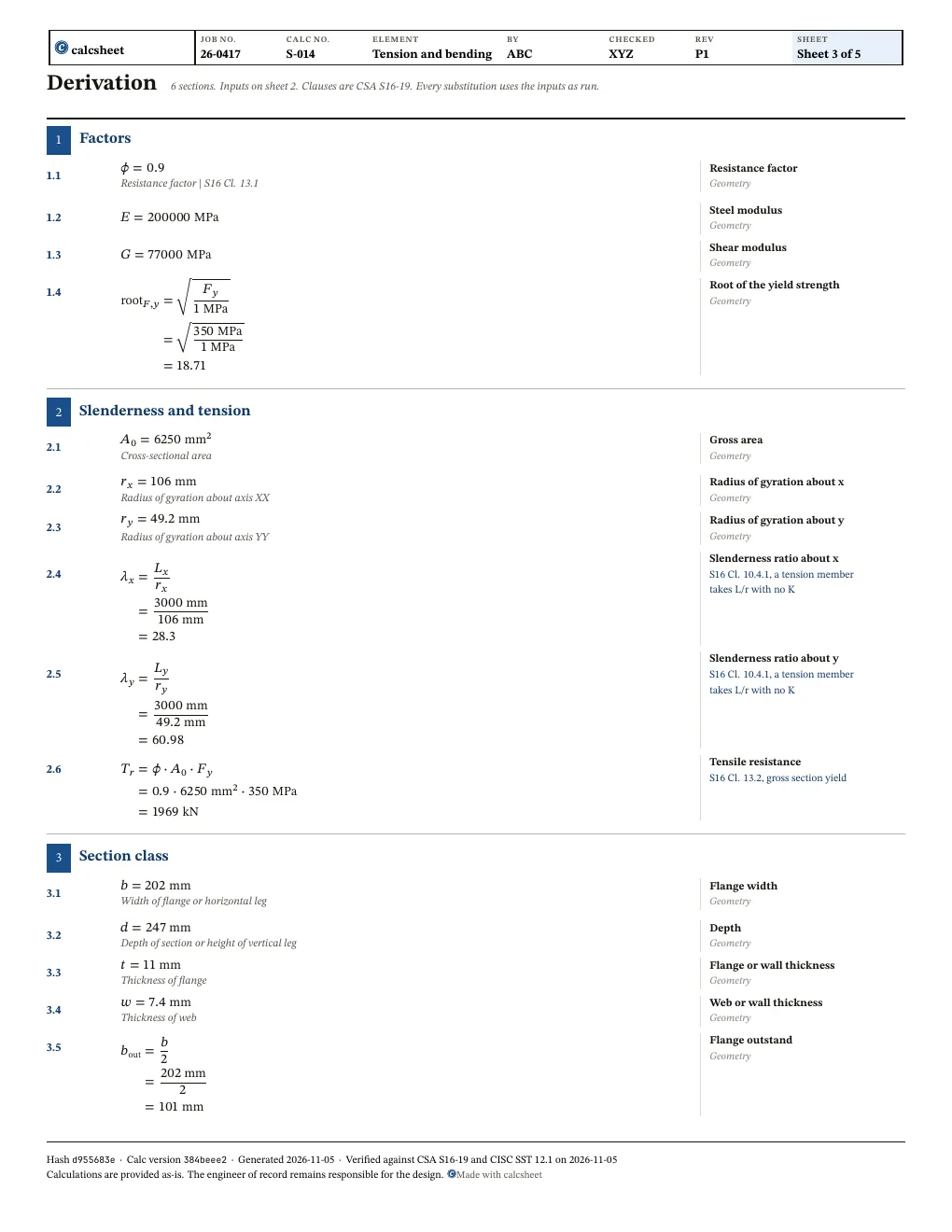
The first sheet of the working in the Tension and bending report: each step with its clause
The working: each step with its clause · full size

Questions

Why does S16 Cl. 13.9 have two interactions?

The first limits the section's strength under both. The second is lateral-torsional buckling, which the tension resists: it takes the unbraced moment resistance and subtracts the tension's share of the compression flange's stress.

Is the net section checked?

No: T_r is the gross section's yield; net section fracture and block shear are not checked.

Revision history

After an independent checker's review: a channel's moment resistance now rests on S_x F_y (Cl. 13.6.1 b) and the channel is capped at class 3, a square HSS takes M_r from Cl. 13.5, a class 4 flange starts from the gross M_y, and the net-section item cites Cl. 13.2 a) iii) and block shear
ValueWasNowUnit
S_x572000mm3\mathrm{mm}^{3}