 calcsheet
 Axial compression of a WT, channel or angle
CSA S16-19Verified against CSA S16-19 and CISC SST 12.1: 18 formulas and 7 clauses compared with the code text, 12 rows accepted by the author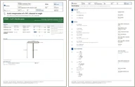
Class 4 effective area and flexural-torsional buckling of a WT, C, MC or single angle. Check a WT, a C or MC channel, or a single angle in concentric compression. Each element is classified, and a class 4 element's excess width comes off the area. The elastic buckling stress is the least root of S16's cubic, which couples twisting with bending about the axes the shear centre is off, and sets the compressive resistance.
First report free, then a free sign-in
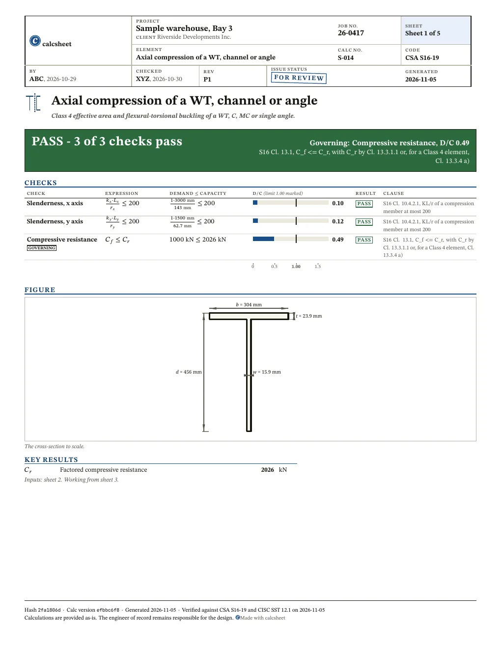
PASS Governing: Compressive resistance, D/C 0.49, S16 Cl. 13.1, C_f <= C_r, with C_r by Cl. 13.3.1.1 or, for a Class 4 element, Cl. 13.3.4 a)3 of 3 checks below pass
Given
Jump to resultsType any value, everything below recomputes. Hover or tap a symbol to trace it.
Resume your last case ()? Load it
This printed copy omits the derivation. The full report, with every step, is the PDF at https://calc.struct.work/calc/axial-open-shapes.pdf.
Checks
! marks a check that passes with D/C at or above 0.95: close to its limit. The band is a site convention, not a code limit.
| Check | D/C | Utilisation | Result |
|---|---|---|---|
| Slenderness, x axisS16 Cl. 10.4.2.1, KL/r of a compression member at most 200 | 0.10 | PASS | |
| Slenderness, y axisS16 Cl. 10.4.2.1, KL/r of a compression member at most 200 | 0.12 | PASS | |
| Compressive resistanceS16 Cl. 13.1, C_f <= C_r, with C_r by Cl. 13.3.1.1 or, for a Class 4 element, Cl. 13.3.4 a) | 0.49 | PASS |
Results
Also worth checking
- Combined axial load and bending, Cl. 13.8 and 13.9: this is concentric compression only
- A WT, channel or angle loaded eccentrically, as through a connected leg or an end gusset, which puts a moment on the member; for a single angle connected through one leg Cl. 13.3.2.1 to 13.3.2.4 take an equivalent slenderness or the eccentricity, and the resistance can be lower than this concentric one (see the single-angle calculator)
- Tension, shear and deflection
- A member whose ends are free to twist: the calc takes K_z = 1.0 and L_z = L_x, which S16 Cl. 13.3.1.2 allows only when both ends are restrained from twisting
- Local effects at the load points and the connections, including bolts and shear lag
- Built-up and non-table sections, double angles and back-to-back channels, and any member out of straightness beyond what S16's column curve assumes
Derivation
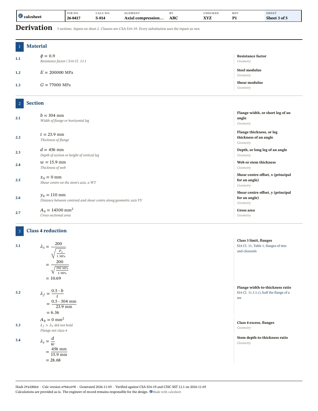
Compared with CSA S16-19 Cl. 13.1 a) (phi = 0.90, structural steel)
S16 Cl. 11, Table 1, flanges of tees and channels
Compared with CSA S16-19 Cl. 11.2 Table 1 / Cl. 13.3.4 a), WT flange b_el/t = 0.5 b/t
S16 Cl. 11.3.1 c), half the flange of a tee
Branch: did not hold
Compared with CSA S16-19 Cl. 11.2 Table 1 / Cl. 13.3.4 a), WT stem b_el/t = d/w
Compared with CSA S16-19 Cl. 11.2 Table 1 (stems of T-sections: 340/sqrt(F_y))
S16 Cl. 11, Table 1, stem of a tee
Branch: held
Compared with CSA S16-19 Cl. 13.3.4 a), area lost to reduced stem width (lambda_s - lambda_3s) w^2
Compared with CSA S16-19 Cl. 13.3.4 a), effective area = gross less reduced widths
S16 Cl. 13.3.4 a), A_e from reduced widths meeting Table 1
S16 Cl. 13.3.1.2, K_z L_z taken as L_x, K_z = 1.0 with both ends restrained from twisting
Compared with CSA S16-19 Cl. 13.3.1.2, r_o^2 = x_o^2 + y_o^2 + r_x^2 + r_y^2
Compared with CSA S16-19 Cl. 13.3.1.2, F_ex = pi^2 E / (K_x L_x / r_x)^2 (1.974 TPa = pi^2 E)
Compared with CSA S16-19 Cl. 13.3.1.2, F_ey = pi^2 E / (K_y L_y / r_y)^2
S16 Cl. 13.3.1.1 (b) or (c), the cubic
Compared with CSA S16-19 Cl. 13.3.1.1, lambda = sqrt(F_y/F_e)
S16 Cl. 13.3.1, n = 1.34
Report
Sheet 1 and the first sheet of the working of the PDF report, at the declared values with a sample title block. First report free, then a free sign-in.
Questions
Which axes are r_x and r_y about for an angle?
The principal axes: r_x and r_y are the major and minor principal radii, and x_0 and y_0 the shear centre's offsets along them.
Why is the torsional length L_x?
The member's length between twisting restraints is taken as the x-axis length. Enter L_x as that length.
Revision history
After an independent checker's review: added slenderness checks of KL/r against 200 on each axis (Cl. 10.4.2.1), cited the class 4 effective area (Cl. 13.3.4 a) and the tee half-flange width, and named the single-angle through-one-leg rule (Cl. 13.3.2) as not checked
| Value | Was | Now | Unit |
|---|---|---|---|
slender_x_ok | |||
slender_y_ok |
fix(units,examples): zero keeps its unit, zero cope, shear tab rules
| Value | Was | Now | Unit |
|---|---|---|---|
x_0 | 0 \mathrm{m} | 0 | |
A_b | 0 \mathrm{m}^{2} | 0 |