SteelDouble angle in tension

Two angles back to back as a tension brace, with the connection's eccentricity, to CSA S16. Check two angles back to back as a brace in tension, vertical with the gusset between them or horizontal with them on it. The gross section's yield and the slenderness are checked; with the connection's eccentricity the pair bends as a tee, its moment resistance is CSA S16 Cl. 13.5's for the pair's class, with AISC 360-22 F9's lateral-torsional buckling, and the tension and moment are combined by CSA S16 Cl. 13.9.

CA$4.00 for this report, or Pro

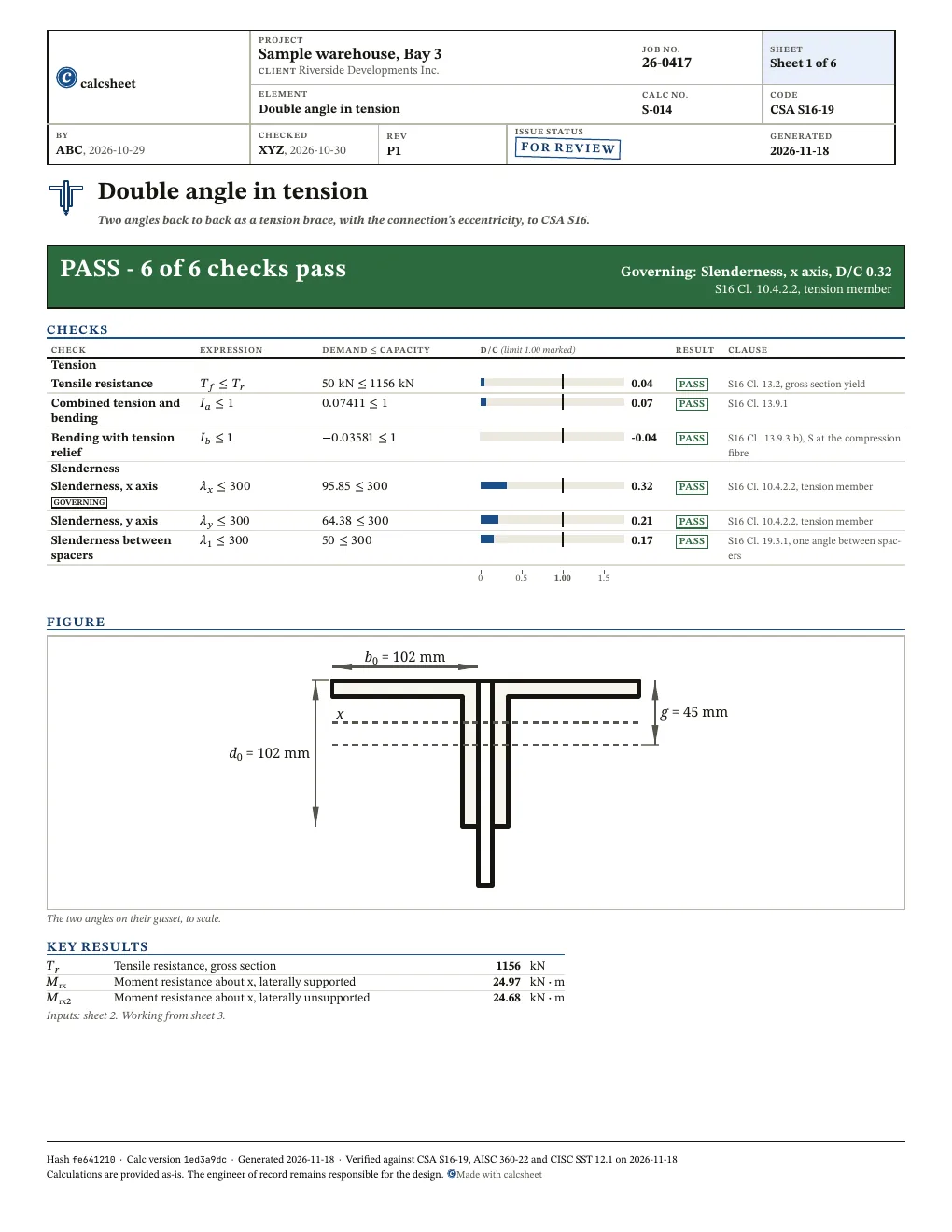
PASS Governing: Slenderness, x axis, D/C 0.32, S16 Cl. 10.4.2.2, tension member6 of 6 checks below pass

x d0 = 102 mm b0 = 102 mm g = 45 mm
The two angles on their gusset, to scale.

Given

Jump to results

Type any value, everything below recomputes. Hover or tap a symbol to trace it.

Loads
changed from the declared value TfT_{f} kN\mathrm{kN}0-20,000
changed from the declared value
Section
changed from the declared value
changed from the declared value FyF_{y} MPa\mathrm{MPa}200-700
Connection
changed from the declared value
changed from the declared value gg mm\mathrm{mm}5-300
changed from the declared value tpt_{p} mm\mathrm{mm}3-60
Bracing
changed from the declared value LxL_{x} mm\mathrm{mm}100-30,000
changed from the declared value LyL_{y} mm\mathrm{mm}100-30,000
changed from the declared value nn 1-20

Title block

Optional. Printed in the title block of the PDF.

Checks

All 6 checks pass. Largest D/C 0.32, Slenderness, x axis.

Show all 6 checks

! marks a check that passes with D/C at or above 0.95: close to its limit. The band is a site convention, not a code limit.

Tension

Check D/C Utilisation Result
Tensile resistanceS16 Cl. 13.2, gross section yieldTf≤Tr⇒50 kN≤1156 kN\htmlClass{sym-T_f}{T_{f}} \leq \htmlClass{sym-T_r}{T_{r}} \quad \Rightarrow \quad \htmlClass{sym-T_f}{50\ \mathrm{kN}} \leq \htmlClass{sym-T_r}{1156\ \mathrm{kN}} 0.04 PASS
Combined tension and bendingS16 Cl. 13.9.1Ia≤1⇒0.07411≤1\htmlClass{sym-I_a}{I_{a}} \leq 1 \quad \Rightarrow \quad \htmlClass{sym-I_a}{0.07411} \leq 1 0.07 PASS
Bending with tension reliefS16 Cl. 13.9.3 b), S at the compression fibreIb≤1⇒−0.03581≤1\htmlClass{sym-I_b}{I_{b}} \leq 1 \quad \Rightarrow \quad \htmlClass{sym-I_b}{-0.03581} \leq 1 -0.04 PASS

Slenderness

Check D/C Utilisation Result
Slenderness, x axisS16 Cl. 10.4.2.2, tension memberλx≤300⇒95.85≤300\htmlClass{sym-lambda_x}{\lambda_{x}} \leq 300 \quad \Rightarrow \quad \htmlClass{sym-lambda_x}{95.85} \leq 300 0.32 PASS
Slenderness, y axisS16 Cl. 10.4.2.2, tension memberλy≤300⇒64.38≤300\htmlClass{sym-lambda_y}{\lambda_{y}} \leq 300 \quad \Rightarrow \quad \htmlClass{sym-lambda_y}{64.38} \leq 300 0.21 PASS
Slenderness between spacersS16 Cl. 19.3.1, one angle between spacersλ1≤300⇒50≤300\htmlClass{sym-lambda_1}{\lambda_{1}} \leq 300 \quad \Rightarrow \quad \htmlClass{sym-lambda_1}{50} \leq 300 0.17 PASS

Results

Quantity Description Value Unit
Tr\htmlClass{sym-T_r}{T_{r}} Tensile resistance, gross section 1156 kN\mathrm{kN}
Mrx\htmlClass{sym-M_rx}{M_{\mathrm{rx}}} Moment resistance about x, laterally supported 24.97 kN⋅m\mathrm{kN} \cdot \mathrm{m}
Mrx2\htmlClass{sym-M_rx2}{M_{\mathrm{rx}2}} Moment resistance about x, laterally unsupported 24.68 kN⋅m\mathrm{kN} \cdot \mathrm{m}
Also worth checking
  • Block shear and net section rupture at the bolts (Cl. 13.2 a) ii) and iii)): the tensile resistance is the gross section's yield
  • The bolts, the gusset plate and the connection, including shear lag
  • The spacers and their connections: only the slenderness of one angle between them (Cl. 19.3.1) is checked; at a 0 mm gap the angles are in contact and Cl. 19.3.3 limits the connector spacing to 600 mm unless a greater spacing is shown acceptable
  • Bending about the weak axis, and a load that is off the gusset's plane in the other direction
  • A row of S16 Table 2 for a double angle's own legs (it has none): the flange legs are classed on the pair-of-angles row at every gap, though the row says in continuous contact, and the stem legs on the stems-of-T-sections row; Z_x is not tabulated, so a Class 1 or 2 pair takes F9's own 1.6 M_y or 1.5 M_y; a flange leg whose face stress T_f/A - M_fx y_c/I_x is tensile is not in compression, so it is not classed on the compression rows and is taken as at most Class 3; AISC F10.3's leg local buckling M_n3 still caps M_rx2 there, which is conservative
  • A Class 4 pair that Cl. 13.5 c) iii) cannot reduce: stem legs in compression over Class 3 (c) iii) reduces only a flange); flange and stem legs both over Class 3 (Cl. 13.5 c) i), sent to CSA S136). The calc refuses each and names the clause
  • Yielding of the pair under service loads (Cl. 13.5 a) and 13.6.1 e)): the moment resistance takes up to 1.6 M_y
  • The connection's eccentricity when Eccentricity considered is No (Cl. 21.1): the member is then checked in axial tension only; check the eccentricity, or the shear lag of Cl. 12.3.3 at the net section, elsewhere
  • Braces of a seismic force resisting system (Cl. 27, e.g. 27.5.2.5 tension-only bracing): its probable resistances, slenderness and capacity-design connection requirements

Derivation

1.1Resistance factor
ϕ=0.9(Resistance factor | S16 Cl. 13.1)\begin{aligned} \htmlClass{sym-phi}{\phi} &= 0.9 \quad \left(\text{Resistance factor | S16 Cl. 13.1}\right) \end{aligned}
1.2Steel modulus

S16 Cl. 3.2, E = 200 000 MPa

E=200000 MPa\begin{aligned} \htmlClass{sym-E}{E} &= 200000\ \mathrm{MPa} \end{aligned}
1.3Outstanding leg, the tee's flange
b0=102 mm(Width of flange or horizontal leg)\begin{aligned} \htmlClass{sym-b_0}{b_{0}} &= 102\ \mathrm{mm} \quad \left(\text{Width of flange or horizontal leg}\right) \end{aligned}
1.4Back-to-back leg, the tee's stem
d0=102 mm(Depth of section or height of vertical leg)\begin{aligned} \htmlClass{sym-d_0}{d_{0}} &= 102\ \mathrm{mm} \quad \left(\text{Depth of section or height of vertical leg}\right) \end{aligned}
1.5Leg thickness
t=11.1 mm(Thickness of flange)\begin{aligned} \htmlClass{sym-t}{t} &= 11.1\ \mathrm{mm} \quad \left(\text{Thickness of flange}\right) \end{aligned}
1.6Area of the pair
A0=4280 mm2(Cross-sectional area)\begin{aligned} \htmlClass{sym-A_0}{A_{0}} &= 4280\ \mathrm{mm}^{2} \quad \left(\text{Cross-sectional area}\right) \end{aligned}
1.7Centroid from the outstanding legs' face
yc=29.6 mm(Vertical distance between centroid and outside face of flange orhorizontal leg)\begin{aligned} \htmlClass{sym-y_c}{y_{c}} &= 29.6\ \mathrm{mm} \quad \left(\text{Vertical distance between centroid and outside face of flange orhorizontal leg}\right) \end{aligned}
1.8Radius of gyration about x
rx=31.3 mm(Radius of gyration about axis XX)\begin{aligned} \htmlClass{sym-r_x}{r_{x}} &= 31.3\ \mathrm{mm} \quad \left(\text{Radius of gyration about axis XX}\right) \end{aligned}

bracing=VERTICAL\mathrm{bracing} = \mathrm{VERTICAL} and tp≤20 mm⇒10 mm≤20 mmt_{p} \leq 20\ \mathrm{mm} \quad \Rightarrow \quad 10\ \mathrm{mm} \leq 20\ \mathrm{mm}

1.9Radius of gyration of the pair about y
ry2=46.6 mm(Radius of gyration about axis YY (10 mm back-to-back))\begin{aligned} \htmlClass{sym-r_y2}{r_{y2}} &= 46.6\ \mathrm{mm} \quad \left(\text{Radius of gyration about axis YY (10 mm back-to-back)}\right) \end{aligned}
1.10Least radius of gyration, one angle
rz=20 mm(Minimum radius of gyration about minor principal axis(single angle))\begin{aligned} \htmlClass{sym-r_z}{r_{z}} &= 20\ \mathrm{mm} \quad \left(\text{Minimum radius of gyration about minor principal axis(single angle)}\right) \end{aligned}
2.1Tensile resistance

S16 Cl. 13.2, gross section yield

Tr=ϕ⋅A0⋅Fy=0.9⋅4280 mm2⋅300 MPa=1156 kN\begin{aligned} \htmlClass{sym-T_r}{T_{r}} &= \htmlClass{sym-phi}{\phi} \cdot \htmlClass{sym-A_0}{A_{0}} \cdot \htmlClass{sym-F_y}{F_{y}} \\ &= \htmlClass{sym-phi}{0.9} \cdot \htmlClass{sym-A_0}{4280\ \mathrm{mm}^{2}} \cdot \htmlClass{sym-F_y}{300\ \mathrm{MPa}} \\ &= 1156\ \mathrm{kN} \end{aligned}
2.2Slenderness ratio about x

S16 Cl. 10.4.1, L/r for a member in tension

λx=Lxrx=3000 mm31.3 mm=95.85\begin{aligned} \htmlClass{sym-lambda_x}{\lambda_{x}} &= \frac{\htmlClass{sym-L_x}{L_{x}}}{\htmlClass{sym-r_x}{r_{x}}} \\ &= \frac{\htmlClass{sym-L_x}{3000\ \mathrm{mm}}}{\htmlClass{sym-r_x}{31.3\ \mathrm{mm}}} \\ &= 95.85 \end{aligned}
2.3Slenderness ratio about y

S16 Cl. 10.4.1, L/r for a member in tension

λy=Lyry2=3000 mm46.6 mm=64.38\begin{aligned} \htmlClass{sym-lambda_y}{\lambda_{y}} &= \frac{\htmlClass{sym-L_y}{L_{y}}}{\htmlClass{sym-r_y2}{r_{y2}}} \\ &= \frac{\htmlClass{sym-L_y}{3000\ \mathrm{mm}}}{\htmlClass{sym-r_y2}{46.6\ \mathrm{mm}}} \\ &= 64.38 \end{aligned}
2.4Slenderness of one angle between spacers

S16 Cl. 19.3.1, one angle between spacers

λ1=max⁡(Lx,Ly)n⋅rz=max⁡(3000 mm,3000 mm)3⋅20 mm=50\begin{aligned} \htmlClass{sym-lambda_1}{\lambda_{1}} &= \frac{\max\left(\htmlClass{sym-L_x}{L_{x}}, \htmlClass{sym-L_y}{L_{y}}\right)}{\htmlClass{sym-n}{n} \cdot \htmlClass{sym-r_z}{r_{z}}} \\ &= \frac{\max\left(\htmlClass{sym-L_x}{3000\ \mathrm{mm}}, \htmlClass{sym-L_y}{3000\ \mathrm{mm}}\right)}{\htmlClass{sym-n}{3} \cdot \htmlClass{sym-r_z}{20\ \mathrm{mm}}} \\ &= 50 \end{aligned}
3.1Torsional constant
J=176000 mm4(St-Venant torsional constant)\begin{aligned} \htmlClass{sym-J}{J} &= 176000\ \mathrm{mm}^{4} \quad \left(\text{St-Venant torsional constant}\right) \end{aligned}
3.2Moment of inertia about x
Ix=4.19×106 mm4(Moment of inertia about axis XX)\begin{aligned} \htmlClass{sym-I_x}{I_{x}} &= 4.19 \times 10^{6}\ \mathrm{mm}^{4} \quad \left(\text{Moment of inertia about axis XX}\right) \end{aligned}
3.3Moment of inertia about y
Iy=ry22⋅A0=(46.6 mm)2⋅4280 mm2=9.294×106 mm4\begin{aligned} \htmlClass{sym-I_y}{I_{y}} &= \htmlClass{sym-r_y2}{r_{y2}}^{2} \cdot \htmlClass{sym-A_0}{A_{0}} \\ &= \left(\htmlClass{sym-r_y2}{46.6\ \mathrm{mm}}\right)^{2} \cdot \htmlClass{sym-A_0}{4280\ \mathrm{mm}^{2}} \\ &= 9.294 \times 10^{6}\ \mathrm{mm}^{4} \end{aligned}
3.4Bolt line to the centroid
ev=∣g−yc∣=∣45 mm−29.6 mm∣=15.4 mm\begin{aligned} \htmlClass{sym-e_v}{e_{v}} &= \left| \htmlClass{sym-g}{g} - \htmlClass{sym-y_c}{y_{c}} \right| \\ &= \left| \htmlClass{sym-g}{45\ \mathrm{mm}} - \htmlClass{sym-y_c}{29.6\ \mathrm{mm}} \right| \\ &= 15.4\ \mathrm{mm} \end{aligned}
3.5Factored moment about x
Mfx=ev⋅Tf=15.4 mm⋅50 kN=0.77 kN⋅m\begin{aligned} \htmlClass{sym-M_fx}{M_{\mathrm{fx}}} &= \htmlClass{sym-e_v}{e_{v}} \cdot \htmlClass{sym-T_f}{T_{f}} \\ &= \htmlClass{sym-e_v}{15.4\ \mathrm{mm}} \cdot \htmlClass{sym-T_f}{50\ \mathrm{kN}} \\ &= 0.77\ \mathrm{kN} \cdot \mathrm{m} \end{aligned}

g≥yc⇒45 mm≥29.6 mmg \geq y_{c} \quad \Rightarrow \quad 45\ \mathrm{mm} \geq 29.6\ \mathrm{mm}

3.6Stem in compression or tension
stem=1(Stem in tension)\begin{aligned} \htmlClass{sym-stem}{\mathrm{stem}} &= 1 \quad \left(\text{Stem in tension}\right) \end{aligned}

stem≤1⇒1≤1\mathrm{stem} \leq 1 \quad \Rightarrow \quad 1 \leq 1

3.7Elastic modulus, tension fibre
Sxt=57800 mm3(Elastic section modulus about axis XX)\begin{aligned} \htmlClass{sym-S_xt}{S_{\mathrm{xt}}} &= 57800\ \mathrm{mm}^{3} \quad \left(\text{Elastic section modulus about axis XX}\right) \end{aligned}
3.8Elastic modulus, compression fibre
Sxc=Ixyc=4.19×106 mm429.6 mm=141554 mm3\begin{aligned} \htmlClass{sym-S_xc}{S_{\mathrm{xc}}} &= \frac{\htmlClass{sym-I_x}{I_{x}}}{\htmlClass{sym-y_c}{y_{c}}} \\ &= \frac{\htmlClass{sym-I_x}{4.19 \times 10^{6}\ \mathrm{mm}^{4}}}{\htmlClass{sym-y_c}{29.6\ \mathrm{mm}}} \\ &= 141554\ \mathrm{mm}^{3} \end{aligned}
3.9Yield moment

AISC 360-22 F9-3

My=Sxt⋅Fy=57800 mm3⋅300 MPa=17.34 kN⋅m\begin{aligned} \htmlClass{sym-M_y}{M_{y}} &= \htmlClass{sym-S_xt}{S_{\mathrm{xt}}} \cdot \htmlClass{sym-F_y}{F_{y}} \\ &= \htmlClass{sym-S_xt}{57800\ \mathrm{mm}^{3}} \cdot \htmlClass{sym-F_y}{300\ \mathrm{MPa}} \\ &= 17.34\ \mathrm{kN} \cdot \mathrm{m} \end{aligned}
3.10Yielding strength

AISC 360-22 F9-1 and F9-2, M_p = 1.6 M_y, under F_y Z_x for every tabulated pair

Mn1=1.6⋅My=1.6⋅17.34 kN⋅m=27.74 kN⋅m\begin{aligned} \htmlClass{sym-M_n1}{M_{n1}} &= 1.6 \cdot \htmlClass{sym-M_y}{M_{y}} \\ &= 1.6 \cdot \htmlClass{sym-M_y}{17.34\ \mathrm{kN} \cdot \mathrm{m}} \\ &= 27.74\ \mathrm{kN} \cdot \mathrm{m} \end{aligned}
4.1Lateral-torsional buckling parameter

AISC 360-22 F9-11

B=2.3⋅d0Ly⋅IyJ=2.3⋅102 mm3000 mm⋅9.294×106 mm4176000 mm4=0.5683\begin{aligned} \htmlClass{sym-B}{B} &= 2.3 \cdot \frac{\htmlClass{sym-d_0}{d_{0}}}{\htmlClass{sym-L_y}{L_{y}}} \cdot \sqrt{\frac{\htmlClass{sym-I_y}{I_{y}}}{\htmlClass{sym-J}{J}}} \\ &= 2.3 \cdot \frac{\htmlClass{sym-d_0}{102\ \mathrm{mm}}}{\htmlClass{sym-L_y}{3000\ \mathrm{mm}}} \cdot \sqrt{\frac{\htmlClass{sym-I_y}{9.294 \times 10^{6}\ \mathrm{mm}^{4}}}{\htmlClass{sym-J}{176000\ \mathrm{mm}^{4}}}} \\ &= 0.5683 \end{aligned}
4.2Elastic lateral-torsional buckling moment

AISC 360-22 F9-10

Mcr=1.95⋅ELy⋅Iy⋅J⋅(B+1+B2)=1.95⋅200000 MPa3000 mm⋅9.294×106 mm4⋅176000 mm4⋅(0.5683+1+0.56832)=285.7 kN⋅m\begin{aligned} \htmlClass{sym-M_cr}{M_{\mathrm{cr}}} &= 1.95 \cdot \frac{\htmlClass{sym-E}{E}}{\htmlClass{sym-L_y}{L_{y}}} \cdot \sqrt{\htmlClass{sym-I_y}{I_{y}} \cdot \htmlClass{sym-J}{J}} \cdot \left(\htmlClass{sym-B}{B} + \sqrt{1 + \htmlClass{sym-B}{B}^{2}}\right) \\ &= 1.95 \cdot \frac{\htmlClass{sym-E}{200000\ \mathrm{MPa}}}{\htmlClass{sym-L_y}{3000\ \mathrm{mm}}} \cdot \sqrt{\htmlClass{sym-I_y}{9.294 \times 10^{6}\ \mathrm{mm}^{4}} \cdot \htmlClass{sym-J}{176000\ \mathrm{mm}^{4}}} \cdot \left(\htmlClass{sym-B}{0.5683} + \sqrt{1 + \htmlClass{sym-B}{0.5683}^{2}}\right) \\ &= 285.7\ \mathrm{kN} \cdot \mathrm{m} \end{aligned}

stem≤1⇒1≤1\mathrm{stem} \leq 1 \quad \Rightarrow \quad 1 \leq 1

4.3Limiting unbraced length, plastic

AISC 360-22 F9-8

Lp=1.76⋅ry2⋅EFy=1.76⋅46.6 mm⋅200000 MPa300 MPa=2118 mm\begin{aligned} \htmlClass{sym-L_p}{L_{p}} &= 1.76 \cdot \htmlClass{sym-r_y2}{r_{y2}} \cdot \sqrt{\frac{\htmlClass{sym-E}{E}}{\htmlClass{sym-F_y}{F_{y}}}} \\ &= 1.76 \cdot \htmlClass{sym-r_y2}{46.6\ \mathrm{mm}} \cdot \sqrt{\frac{\htmlClass{sym-E}{200000\ \mathrm{MPa}}}{\htmlClass{sym-F_y}{300\ \mathrm{MPa}}}} \\ &= 2118\ \mathrm{mm} \end{aligned}
4.4Limiting unbraced length, inelastic

AISC 360-22 F9-9

Lr=1.95⋅EFy⋅Iy⋅JSxt⋅2.36⋅FyE⋅d0⋅SxtJ+1=1.95⋅200000 MPa300 MPa⋅9.294×106 mm4⋅176000 mm457800 mm3⋅2.36⋅300 MPa200000 MPa⋅102 mm⋅57800 mm3176000 mm4+1=30424 mm\begin{aligned} \htmlClass{sym-L_r}{L_{r}} &= \frac{1.95 \cdot \frac{\htmlClass{sym-E}{E}}{\htmlClass{sym-F_y}{F_{y}}} \cdot \sqrt{\htmlClass{sym-I_y}{I_{y}} \cdot \htmlClass{sym-J}{J}}}{\htmlClass{sym-S_xt}{S_{\mathrm{xt}}}} \cdot \sqrt{\frac{2.36 \cdot \frac{\htmlClass{sym-F_y}{F_{y}}}{\htmlClass{sym-E}{E}} \cdot \htmlClass{sym-d_0}{d_{0}} \cdot \htmlClass{sym-S_xt}{S_{\mathrm{xt}}}}{\htmlClass{sym-J}{J}} + 1} \\ &= \frac{1.95 \cdot \frac{\htmlClass{sym-E}{200000\ \mathrm{MPa}}}{\htmlClass{sym-F_y}{300\ \mathrm{MPa}}} \cdot \sqrt{\htmlClass{sym-I_y}{9.294 \times 10^{6}\ \mathrm{mm}^{4}} \cdot \htmlClass{sym-J}{176000\ \mathrm{mm}^{4}}}}{\htmlClass{sym-S_xt}{57800\ \mathrm{mm}^{3}}} \cdot \sqrt{\frac{2.36 \cdot \frac{\htmlClass{sym-F_y}{300\ \mathrm{MPa}}}{\htmlClass{sym-E}{200000\ \mathrm{MPa}}} \cdot \htmlClass{sym-d_0}{102\ \mathrm{mm}} \cdot \htmlClass{sym-S_xt}{57800\ \mathrm{mm}^{3}}}{\htmlClass{sym-J}{176000\ \mathrm{mm}^{4}}} + 1} \\ &= 30424\ \mathrm{mm} \end{aligned}

Ly>Lp⇒3000 mm>2118 mmL_{y} > L_{p} \quad \Rightarrow \quad 3000\ \mathrm{mm} > 2118\ \mathrm{mm}

Ly≤Lr⇒3000 mm≤30424 mmL_{y} \leq L_{r} \quad \Rightarrow \quad 3000\ \mathrm{mm} \leq 30424\ \mathrm{mm}

4.5Lateral-torsional buckling strength

AISC 360-22 F9-6

Mn2=Mn1−(Mn1−My)⋅(Ly−Lp)Lr−Lp=27.74 kN⋅m−(27.74 kN⋅m−17.34 kN⋅m)⋅(3000 mm−2118 mm)30424 mm−2118 mm=27.42 kN⋅m\begin{aligned} \htmlClass{sym-M_n2}{M_{n2}} &= \htmlClass{sym-M_n1}{M_{n1}} - \frac{\left(\htmlClass{sym-M_n1}{M_{n1}} - \htmlClass{sym-M_y}{M_{y}}\right) \cdot \left(\htmlClass{sym-L_y}{L_{y}} - \htmlClass{sym-L_p}{L_{p}}\right)}{\htmlClass{sym-L_r}{L_{r}} - \htmlClass{sym-L_p}{L_{p}}} \\ &= \htmlClass{sym-M_n1}{27.74\ \mathrm{kN} \cdot \mathrm{m}} - \frac{\left(\htmlClass{sym-M_n1}{27.74\ \mathrm{kN} \cdot \mathrm{m}} - \htmlClass{sym-M_y}{17.34\ \mathrm{kN} \cdot \mathrm{m}}\right) \cdot \left(\htmlClass{sym-L_y}{3000\ \mathrm{mm}} - \htmlClass{sym-L_p}{2118\ \mathrm{mm}}\right)}{\htmlClass{sym-L_r}{30424\ \mathrm{mm}} - \htmlClass{sym-L_p}{2118\ \mathrm{mm}}} \\ &= 27.42\ \mathrm{kN} \cdot \mathrm{m} \end{aligned}
5.1Root of the yield strength
rootF,y=Fy1 MPa=300 MPa1 MPa=17.32\begin{aligned} \htmlClass{sym-root_F_y}{\mathrm{root}_{F,y}} &= \sqrt{\frac{\htmlClass{sym-F_y}{F_{y}}}{1\ \mathrm{MPa}}} \\ &= \sqrt{\frac{\htmlClass{sym-F_y}{300\ \mathrm{MPa}}}{1\ \mathrm{MPa}}} \\ &= 17.32 \end{aligned}

stem≤1⇒1≤1\mathrm{stem} \leq 1 \quad \Rightarrow \quad 1 \leq 1

5.2Leg width-to-thickness ratio
λl=b0t=102 mm11.1 mm=9.189\begin{aligned} \htmlClass{sym-lambda_l}{\lambda_{l}} &= \frac{\htmlClass{sym-b_0}{b_{0}}}{\htmlClass{sym-t}{t}} \\ &= \frac{\htmlClass{sym-b_0}{102\ \mathrm{mm}}}{\htmlClass{sym-t}{11.1\ \mathrm{mm}}} \\ &= 9.189 \end{aligned}
5.3Class 3 limit

S16 Table 2, outstanding legs of pairs of angles, Class 3

λc3=200rootF,y=20017.32=11.55\begin{aligned} \htmlClass{sym-lambda_c3}{\lambda_{c3}} &= \frac{200}{\htmlClass{sym-root_F_y}{\mathrm{root}_{F,y}}} \\ &= \frac{200}{\htmlClass{sym-root_F_y}{17.32}} \\ &= 11.55 \end{aligned}
5.4Class 1 limit

S16 Table 2, Class 1 of both rows

λc1=145rootF,y=14517.32=8.372\begin{aligned} \htmlClass{sym-lambda_c1}{\lambda_{c1}} &= \frac{145}{\htmlClass{sym-root_F_y}{\mathrm{root}_{F,y}}} \\ &= \frac{145}{\htmlClass{sym-root_F_y}{17.32}} \\ &= 8.372 \end{aligned}
5.5Class 2 limit

S16 Table 2, Class 2 of both rows

λc2=170rootF,y=17017.32=9.815\begin{aligned} \htmlClass{sym-lambda_c2}{\lambda_{c2}} &= \frac{170}{\htmlClass{sym-root_F_y}{\mathrm{root}_{F,y}}} \\ &= \frac{170}{\htmlClass{sym-root_F_y}{17.32}} \\ &= 9.815 \end{aligned}

λl>λc1⇒9.189>8.372\lambda_{l} > \lambda_{c1} \quad \Rightarrow \quad 9.189 > 8.372

λl≤λc2⇒9.189≤9.815\lambda_{l} \leq \lambda_{c2} \quad \Rightarrow \quad 9.189 \leq 9.815

5.6Class of the leg in compression (S16 Table 2)
legclass=2(Class 2)\begin{aligned} \htmlClass{sym-leg_class}{\mathrm{leg}_{\mathrm{class}}} &= 2 \quad \left(\text{Class 2}\right) \end{aligned}
6.1Compact limit

AISC 360-22 Table B4.1b case 12, legs of angles

λp=0.54⋅EFy=0.54⋅200000 MPa300 MPa=13.94\begin{aligned} \htmlClass{sym-lambda_p}{\lambda_{p}} &= 0.54 \cdot \sqrt{\frac{\htmlClass{sym-E}{E}}{\htmlClass{sym-F_y}{F_{y}}}} \\ &= 0.54 \cdot \sqrt{\frac{\htmlClass{sym-E}{200000\ \mathrm{MPa}}}{\htmlClass{sym-F_y}{300\ \mathrm{MPa}}}} \\ &= 13.94 \end{aligned}
6.2Noncompact limit

AISC 360-22 Table B4.1b case 12, legs of angles

λr=0.91⋅EFy=0.91⋅200000 MPa300 MPa=23.5\begin{aligned} \htmlClass{sym-lambda_r}{\lambda_{r}} &= 0.91 \cdot \sqrt{\frac{\htmlClass{sym-E}{E}}{\htmlClass{sym-F_y}{F_{y}}}} \\ &= 0.91 \cdot \sqrt{\frac{\htmlClass{sym-E}{200000\ \mathrm{MPa}}}{\htmlClass{sym-F_y}{300\ \mathrm{MPa}}}} \\ &= 23.5 \end{aligned}

λl≤λp⇒9.189≤13.94\lambda_{l} \leq \lambda_{p} \quad \Rightarrow \quad 9.189 \leq 13.94

6.3Leg local buckling strength

AISC 360-22 F10.3(a), compact leg: does not apply

Mn3=Mn1=27.74 kN⋅m\begin{aligned} \htmlClass{sym-M_n3}{M_{n3}} &= \htmlClass{sym-M_n1}{M_{n1}} \\ &= 27.74\ \mathrm{kN} \cdot \mathrm{m} \end{aligned}
6.4Nominal moment about x

AISC 360-22 F9, the lowest of the limit states

Mnx=min⁡(Mn1,Mn2,Mn3)=min⁡(27.74 kN⋅m,27.42 kN⋅m,27.74 kN⋅m)=27.42 kN⋅m\begin{aligned} \htmlClass{sym-M_nx}{M_{\mathrm{nx}}} &= \min\left(\htmlClass{sym-M_n1}{M_{n1}}, \htmlClass{sym-M_n2}{M_{n2}}, \htmlClass{sym-M_n3}{M_{n3}}\right) \\ &= \min\left(\htmlClass{sym-M_n1}{27.74\ \mathrm{kN} \cdot \mathrm{m}}, \htmlClass{sym-M_n2}{27.42\ \mathrm{kN} \cdot \mathrm{m}}, \htmlClass{sym-M_n3}{27.74\ \mathrm{kN} \cdot \mathrm{m}}\right) \\ &= 27.42\ \mathrm{kN} \cdot \mathrm{m} \end{aligned}
6.5Smaller elastic modulus about x
Smin=min⁡(Sxt,Sxc)=min⁡(57800 mm3,141554 mm3)=57800 mm3\begin{aligned} \htmlClass{sym-S_min}{S_{\mathrm{min}}} &= \min\left(\htmlClass{sym-S_xt}{S_{\mathrm{xt}}}, \htmlClass{sym-S_xc}{S_{\mathrm{xc}}}\right) \\ &= \min\left(\htmlClass{sym-S_xt}{57800\ \mathrm{mm}^{3}}, \htmlClass{sym-S_xc}{141554\ \mathrm{mm}^{3}}\right) \\ &= 57800\ \mathrm{mm}^{3} \end{aligned}

legclass≤2⇒2≤2\mathrm{leg}_{\mathrm{class}} \leq 2 \quad \Rightarrow \quad 2 \leq 2

6.6Moment resistance about x, laterally supported, Cl. 13.5

S16 Cl. 13.5 a), phi Z F_y, which F9's 1.6 M_y or 1.5 M_y stays under

Mrx=ϕ⋅min⁡(Mn1,Mn3)=0.9⋅min⁡(27.74 kN⋅m,27.74 kN⋅m)=24.97 kN⋅m\begin{aligned} \htmlClass{sym-M_rx}{M_{\mathrm{rx}}} &= \htmlClass{sym-phi}{\phi} \cdot \min\left(\htmlClass{sym-M_n1}{M_{n1}}, \htmlClass{sym-M_n3}{M_{n3}}\right) \\ &= \htmlClass{sym-phi}{0.9} \cdot \min\left(\htmlClass{sym-M_n1}{27.74\ \mathrm{kN} \cdot \mathrm{m}}, \htmlClass{sym-M_n3}{27.74\ \mathrm{kN} \cdot \mathrm{m}}\right) \\ &= 24.97\ \mathrm{kN} \cdot \mathrm{m} \end{aligned}
6.7Moment resistance about x, laterally unsupported, Cl. 13.6.1

S16 Cl. 13.6.1 e), the rational method of F9, never above Cl. 13.5's

Mrx2=min⁡(ϕ⋅Mnx,Mrx)=min⁡(0.9⋅27.42 kN⋅m,24.97 kN⋅m)=24.68 kN⋅m\begin{aligned} \htmlClass{sym-M_rx2}{M_{\mathrm{rx}2}} &= \min\left(\htmlClass{sym-phi}{\phi} \cdot \htmlClass{sym-M_nx}{M_{\mathrm{nx}}}, \htmlClass{sym-M_rx}{M_{\mathrm{rx}}}\right) \\ &= \min\left(\htmlClass{sym-phi}{0.9} \cdot \htmlClass{sym-M_nx}{27.42\ \mathrm{kN} \cdot \mathrm{m}}, \htmlClass{sym-M_rx}{24.97\ \mathrm{kN} \cdot \mathrm{m}}\right) \\ &= 24.68\ \mathrm{kN} \cdot \mathrm{m} \end{aligned}
7.1Tension and bending interaction

S16 Cl. 13.9.1

Ia=TfTr+MfxMrx=50 kN1156 kN+0.77 kN⋅m24.97 kN⋅m=0.07411\begin{aligned} \htmlClass{sym-I_a}{I_{a}} &= \frac{\htmlClass{sym-T_f}{T_{f}}}{\htmlClass{sym-T_r}{T_{r}}} + \frac{\htmlClass{sym-M_fx}{M_{\mathrm{fx}}}}{\htmlClass{sym-M_rx}{M_{\mathrm{rx}}}} \\ &= \frac{\htmlClass{sym-T_f}{50\ \mathrm{kN}}}{\htmlClass{sym-T_r}{1156\ \mathrm{kN}}} + \frac{\htmlClass{sym-M_fx}{0.77\ \mathrm{kN} \cdot \mathrm{m}}}{\htmlClass{sym-M_rx}{24.97\ \mathrm{kN} \cdot \mathrm{m}}} \\ &= 0.07411 \end{aligned}
7.2Bending less tension interaction

S16 Cl. 13.9.3 b), S at the compression fibre

Ib=MfxMrx2−Tf⋅SxcMrx2⋅A0=0.77 kN⋅m24.68 kN⋅m−50 kN⋅141554 mm324.68 kN⋅m⋅4280 mm2=−0.03581\begin{aligned} \htmlClass{sym-I_b}{I_{b}} &= \frac{\htmlClass{sym-M_fx}{M_{\mathrm{fx}}}}{\htmlClass{sym-M_rx2}{M_{\mathrm{rx}2}}} - \frac{\htmlClass{sym-T_f}{T_{f}} \cdot \htmlClass{sym-S_xc}{S_{\mathrm{xc}}}}{\htmlClass{sym-M_rx2}{M_{\mathrm{rx}2}} \cdot \htmlClass{sym-A_0}{A_{0}}} \\ &= \frac{\htmlClass{sym-M_fx}{0.77\ \mathrm{kN} \cdot \mathrm{m}}}{\htmlClass{sym-M_rx2}{24.68\ \mathrm{kN} \cdot \mathrm{m}}} - \frac{\htmlClass{sym-T_f}{50\ \mathrm{kN}} \cdot \htmlClass{sym-S_xc}{141554\ \mathrm{mm}^{3}}}{\htmlClass{sym-M_rx2}{24.68\ \mathrm{kN} \cdot \mathrm{m}} \cdot \htmlClass{sym-A_0}{4280\ \mathrm{mm}^{2}}} \\ &= -0.03581 \end{aligned}

Report

Sheet 1 and the first sheet of the working of the PDF report, at the declared values with a sample title block. Pro.
Show the two sheets
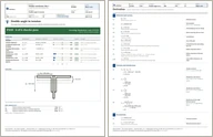
Sheet 1 of the Double angle in tension report: title block, verdict, checks and figures
Sheet 1: title block, verdict, checks, figures · full size
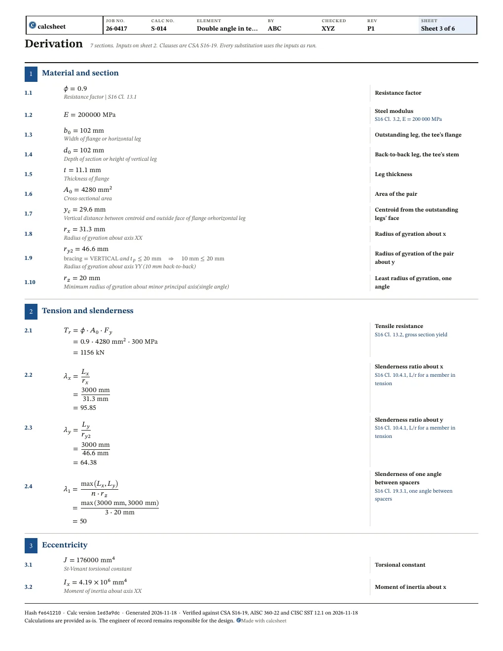
The first sheet of the working in the Double angle in tension report: each step with its clause
The working: each step with its clause · full size

Questions

When is the stem in tension?

In a vertical brace, when the bolt gauge from the flange's face is at or below the centroid; above it, and always in a horizontal brace, the stem is in compression.

Is the net section checked?

No: T_r is the gross section's yield. Check the net section at the bolts with the connection.

Revision history

After an independent checker's review: the first interaction takes the Class 3 moment resistance of S16 Cl. 13.5 (Class 4 refused) and the second takes Cl. 13.6.1's, so the second can fail alone, a bolt gauge off the stem is refused, the gap is drawn at its own value, and the spacer limit (Cl. 19.3.3) is listed as not checked
ValueWasNowUnit
root_F_y17.3205
lambda_c311.547
lambda_c18.37158
lambda_c29.81495
leg_class2
S_min57800mm3\mathrm{mm}^{3}
M_rx24.677724.9696kN⋅m\mathrm{kN} \cdot \mathrm{m}
M_rx224.6777kN⋅m\mathrm{kN} \cdot \mathrm{m}
I_a0.07446980.0741051