 calcsheet
 Connection transfer force
AISC Steel Construction Manual, 14th ed., uniform force methodVerified against AISC Steel Construction Manual, 14th ed.: 15 formulas and 1 clause compared with the code text, 8 rows from definitions, statics and tables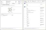
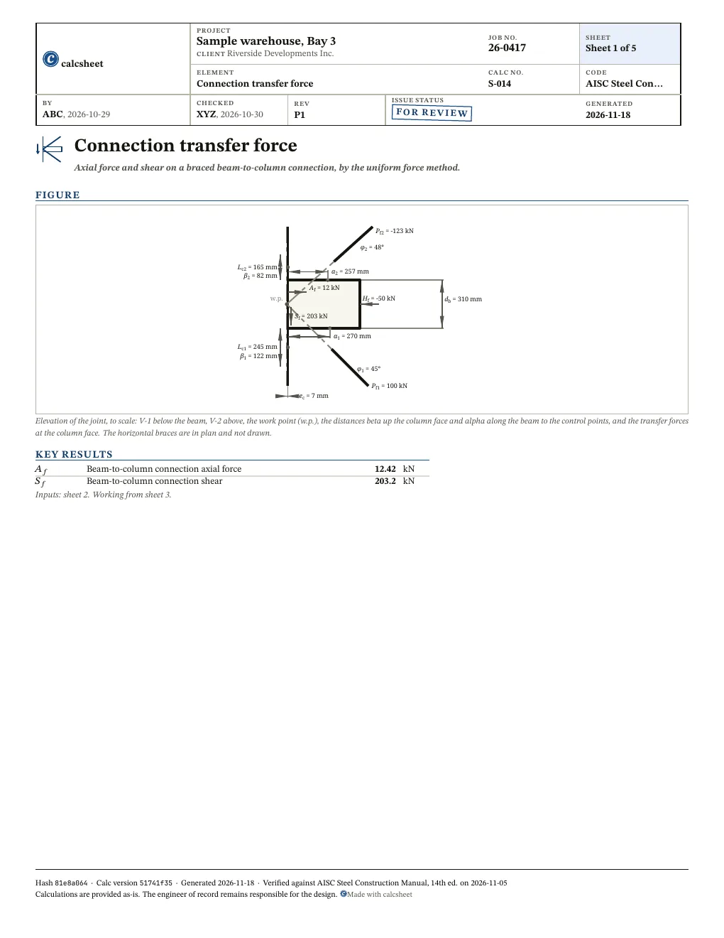
Axial force and shear on a braced beam-to-column connection, by the uniform force method. Resolve the forces meeting at a braced beam-to-column joint into the axial force and shear on the connection to the column. Each vertical brace is split by the uniform force method into the share its gusset delivers along the beam and across it, and the horizontal braces add their component along the beam. The beam's own axial force and shear complete the sums.
First report free, then a free sign-in
Given
Jump to resultsType any value, everything below recomputes. Hover or tap a symbol to trace it.
Resume your last case ()? Load it
This printed copy omits the derivation. The full report, with every step, is the PDF at https://calc.struct.work/calc/connection-transfer-force.pdf.
Results
Also worth checking
- The gusset-to-beam and gusset-to-column bolts or welds, the beam-to-column connection for A_f combined with S_f (S16-19 Cl. 21.2), the gusset plate, the beam web under V_b and the column web or flange: the page resolves forces and sizes nothing that carries them
- The gusset-to-beam connection is taken as detailed with its centroid at alpha and the gusset-to-column bolt group as starting at the beam flange; any other centroid puts a moment M_b = V_b (alpha - alpha_bar) on the gusset-to-beam interface (AISC Manual Eq. 13-17), which this page does not compute
- The horizontal braces' components across the beam, P sin(phi), and their connection to the beam: only the component along the beam is carried into A_f, on the assumption that the braces meet the beam and not the column
- Whether the brace angles and gusset lengths give a joint whose lines of action meet at one point: the geometry is taken as entered
- Equilibrium of the joint as a whole: the brace, beam and column forces are inputs, not read from an analysis
- Load combinations and capacity-based seismic forces: the forces entered are used as factored
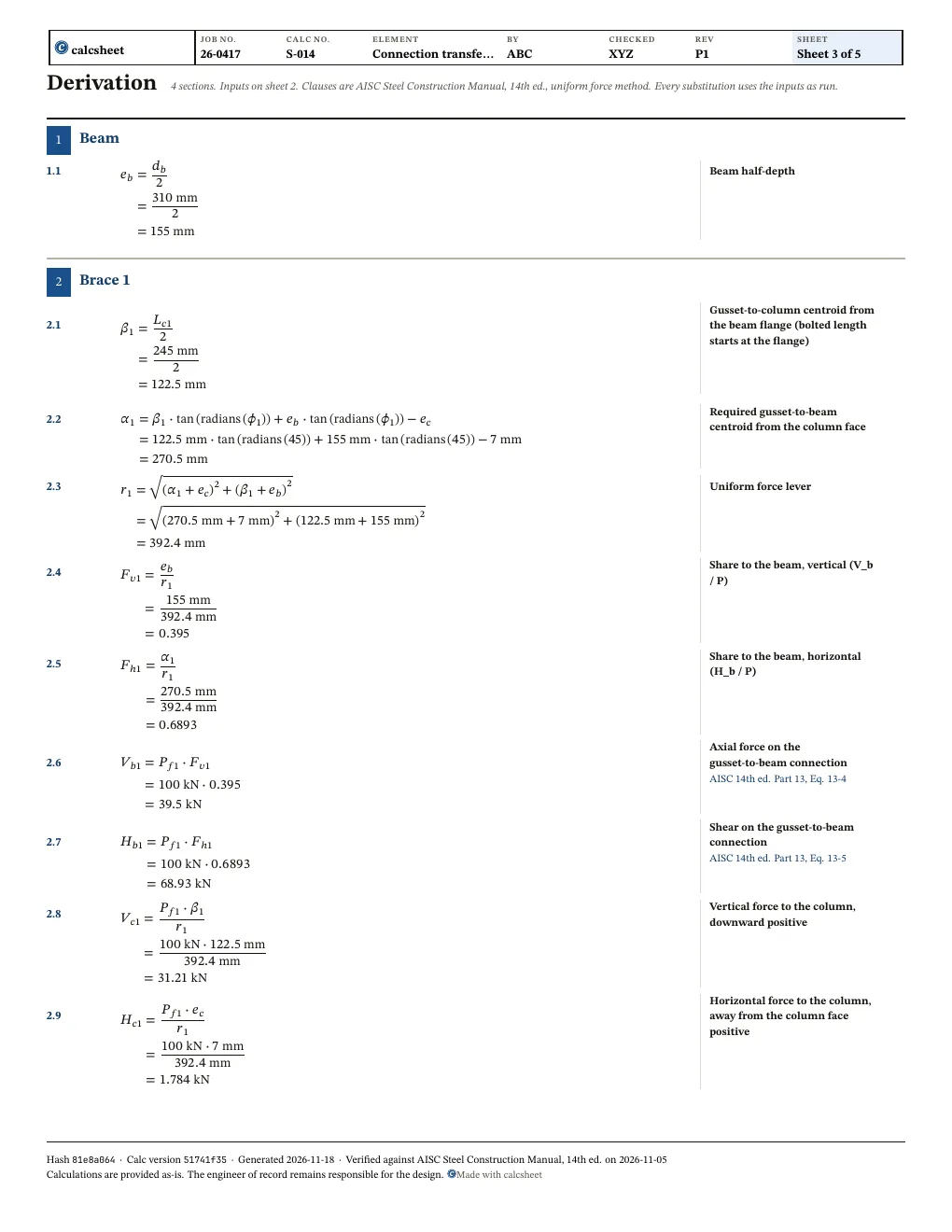
Derivation
Report
Sheet 1 and the first sheet of the working of the PDF report, at the declared values with a sample title block. First report free, then a free sign-in.
Questions
What is e_c?
The distance from the column's centreline to the face the gusset bolts to: half the column depth when the beam frames into the flange, half the web thickness when it frames into the web.
Which brace carries P_f1, and what are phi_1 and phi_3 measured from?
V-1 is the vertical brace below the beam and V-2 the one above it, with their angles measured from the column. H-1 and H-2 are horizontal braces in plan, measured from the beam.
What do I enter for H_f?
The axial force in the beam beyond the gussets, the collector force that carries the braces' horizontal components (A_b - H in AISC Fig. 13-2(d)), tension positive. It is not the manual's A_b, the transverse force from the adjacent bay: A_f = H_f + H_b1 + H_b2 + the plan terms equals the manual's A_b +/- (H - H_b) when H_f = A_b - H.
What sign do A_f, S_f and the brace forces take?
Tension is positive in every brace and in the beam's axial force; the beam's shear is positive downward. A positive A_f pulls the connection off the column.
Revision history
After an independent checker's review: H_f is now labelled and drawn as the beam's axial force beyond the gussets, a joint with zero or negative alpha is refused (Eq. 13-1), V_b and H_b print in kN, and the gusset-to-beam and beam-to-column connections are listed as not checked
| Value | Was | Now | Unit |
|---|---|---|---|
V_b1 | 39.4961 | ||
H_b1 | 68.927 | ||
V_b2 | -53.7136 | ||
H_b2 | -88.981 |