SteelAxial compression of a W section or HSS

Class 4 effective area and the least of flexural and torsional buckling, W shape or HSS. Check a W, WWF, S, HP or M shape or a rectangular or square HSS in concentric compression. Each element is classified and a class 4 element's excess width comes off the area. The elastic buckling stress is the least of flexural buckling about either axis and torsional buckling, and sets the compressive resistance.

First report free, then a free sign-in

PASS Governing: Compressive resistance, D/C 0.78, S16 Cl. 13.1, C_r >= C_f3 of 3 checks below pass

Given

Jump to results

Type any value, everything below recomputes. Hover or tap a symbol to trace it.

Loads
changed from the declared value CfC_{f} kN\mathrm{kN} 0-50,000
Section
changed from the declared value
changed from the declared value FyF_{y} MPa\mathrm{MPa} 200-700
Buckling about x
changed from the declared value LxL_{x} mm\mathrm{mm} 100-20,000
changed from the declared value kxk_{x} 0.5-2.5
Buckling about y
changed from the declared value LyL_{y} mm\mathrm{mm} 100-20,000
changed from the declared value kyk_{y} 0.5-2.5
d = 252 mm b = 203 mm t = 13.5 mm w = 8.0 mm x y
The cross-section to scale.

Title block

Optional. Printed in the title block of the PDF.

Checks

! marks a check that passes with D/C at or above 0.95: close to its limit. The band is a site convention, not a code limit.

Check D/C Utilisation Result
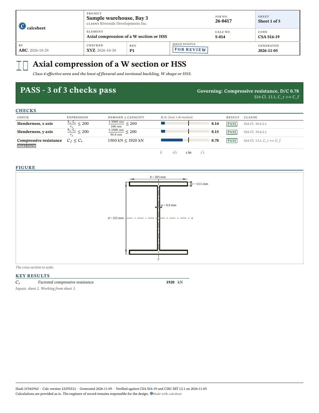
Slenderness, x axisS16 Cl. 10.4.2.1kx⋅Lxrx≤200⇒1⋅3000 mm108 mm≤200\frac{\htmlClass{sym-k_x}{k_{x}} \cdot \htmlClass{sym-L_x}{L_{x}}}{\htmlClass{sym-r_x}{r_{x}}} \leq 200 \quad \Rightarrow \quad \frac{\htmlClass{sym-k_x}{1} \cdot \htmlClass{sym-L_x}{3000\ \mathrm{mm}}}{\htmlClass{sym-r_x}{108\ \mathrm{mm}}} \leq 200 0.14 PASS
Slenderness, y axisS16 Cl. 10.4.2.1ky⋅Lyry≤200⇒1⋅1500 mm50.4 mm≤200\frac{\htmlClass{sym-k_y}{k_{y}} \cdot \htmlClass{sym-L_y}{L_{y}}}{\htmlClass{sym-r_y}{r_{y}}} \leq 200 \quad \Rightarrow \quad \frac{\htmlClass{sym-k_y}{1} \cdot \htmlClass{sym-L_y}{1500\ \mathrm{mm}}}{\htmlClass{sym-r_y}{50.4\ \mathrm{mm}}} \leq 200 0.15 PASS
Compressive resistanceS16 Cl. 13.1, C_r >= C_fCf≤Cr⇒1500 kN≤1920 kN\htmlClass{sym-C_f}{C_{f}} \leq \htmlClass{sym-C_r}{C_{r}} \quad \Rightarrow \quad \htmlClass{sym-C_f}{1500\ \mathrm{kN}} \leq \htmlClass{sym-C_r}{1920\ \mathrm{kN}} 0.78 PASS

Results

Quantity Description Value Unit
Cr\htmlClass{sym-C_r}{C_{r}} Factored compressive resistance 1920 kN\mathrm{kN}
Also worth checking
  • Combined axial load and bending, Cl. 13.8 and 13.9: this is concentric compression only
  • Tension, shear and deflection
  • Twisting at the ends: the torsional length K_z L_z is taken as L_x with K_z = 1.0, which Cl. 13.3.1.2 allows only where both ends are restrained from twisting (Cl. 9.4); a member free to twist at an end, such as a cantilever column, takes a larger K_z L_z
  • The braces and supports that set L_x and L_y: their strength (0.02 times C_f at each brace point) and stiffness, Cl. 9.5 and 9.6, and twist restraint at the supports, Cl. 9.4
  • A 350W Class H HSS or a flame-cut welded I-shape, whose n = 2.24 in Cl. 13.3.1.1 the calc does not take; it takes n = 1.34 throughout
  • Local effects at the load points, such as web crippling and bearing, and the connections
  • Built-up and non-table sections, and any member out of straightness beyond what S16's column curve assumes

Derivation

S.1 Resistance factor

Compared with CSA S16-19 Cl. 13.1 a) (phi = 0.90, structural steel)

ϕ=0.9(Resistance factor | S16 Cl. 13.1)\begin{aligned} \htmlClass{sym-phi}{\phi} &= 0.9 \quad \left(\text{Resistance factor | S16 Cl. 13.1}\right) \end{aligned}
S.2 Steel modulus

Compared with CSA S16-19 Cl. 3, symbols (E = 200 000 MPa assumed)

E=200000 MPa\begin{aligned} \htmlClass{sym-E}{E} &= 200000\ \mathrm{MPa} \end{aligned}
S.3 Shear modulus

Compared with CSA S16-19 Cl. 3, symbols (G = 77 000 MPa assumed)

G=77000 MPa\begin{aligned} \htmlClass{sym-G}{G} &= 77000\ \mathrm{MPa} \end{aligned}
S.4 Table 1 limit, webs and walls

Compared with CSA S16-19 Cl. 11.2 Table 1 (webs of I-shapes and sidewalls of rectangular HSS: 670/sqrt(F_y))

S16 Cl. 11, Table 1, webs and HSS walls in compression

λ3w=670Fy1 MPa=670350 MPa1 MPa=35.81\begin{aligned} \htmlClass{sym-lambda_3w}{\lambda_{3w}} &= \frac{670}{\sqrt{\frac{\htmlClass{sym-F_y}{F_{y}}}{1\ \mathrm{MPa}}}} \\ &= \frac{670}{\sqrt{\frac{\htmlClass{sym-F_y}{350\ \mathrm{MPa}}}{1\ \mathrm{MPa}}}} \\ &= 35.81 \end{aligned}
S.5 Width

Accepted by the author: CISC SST 12.1 section table value (sections-data/cisc_12.1/), a given and not a formula; an HSS wall is the table's design thickness Tdes; W250x58 B

b=203 mm(Width of flange or horizontal leg)\begin{aligned} \htmlClass{sym-b}{b} &= 203\ \mathrm{mm} \quad \left(\text{Width of flange or horizontal leg}\right) \end{aligned}
S.6 Flange or wall thickness

Accepted by the author: CISC SST 12.1 section table value (sections-data/cisc_12.1/), a given and not a formula; an HSS wall is the table's design thickness Tdes; W250x58 T

t=13.5 mm(Thickness of flange)\begin{aligned} \htmlClass{sym-t}{t} &= 13.5\ \mathrm{mm} \quad \left(\text{Thickness of flange}\right) \end{aligned}
S.7 Depth

Accepted by the author: CISC SST 12.1 section table value (sections-data/cisc_12.1/), a given and not a formula; an HSS wall is the table's design thickness Tdes; W250x58 D

d=252 mm(Depth of section or height of vertical leg)\begin{aligned} \htmlClass{sym-d}{d} &= 252\ \mathrm{mm} \quad \left(\text{Depth of section or height of vertical leg}\right) \end{aligned}
S.8 Web or wall thickness

Accepted by the author: CISC SST 12.1 section table value (sections-data/cisc_12.1/), a given and not a formula; an HSS wall is the table's design thickness Tdes; W250x58 W

w=8 mm(Thickness of web)\begin{aligned} \htmlClass{sym-w}{w} &= 8\ \mathrm{mm} \quad \left(\text{Thickness of web}\right) \end{aligned}
S.9 Flange width-to-thickness ratio

Compared with CSA S16-19 Cl. 11.3.1 c) (flange of beam or T-section: b_el = half the full width)

λf=0.5⋅bt=0.5⋅203 mm13.5 mm=7.519\begin{aligned} \htmlClass{sym-lambda_f}{\lambda_{f}} &= \frac{0.5 \cdot \htmlClass{sym-b}{b}}{\htmlClass{sym-t}{t}} \\ &= \frac{0.5 \cdot \htmlClass{sym-b}{203\ \mathrm{mm}}}{\htmlClass{sym-t}{13.5\ \mathrm{mm}}} \\ &= 7.519 \end{aligned}
S.10 Table 1 limit, flanges

Compared with CSA S16-19 Cl. 11.2 Table 1 (flanges of I-sections: 200/sqrt(F_y))

S16 Cl. 11, Table 1, flanges

λ3=200Fy1 MPa=200350 MPa1 MPa=10.69\begin{aligned} \htmlClass{sym-lambda_3}{\lambda_{3}} &= \frac{200}{\sqrt{\frac{\htmlClass{sym-F_y}{F_{y}}}{1\ \mathrm{MPa}}}} \\ &= \frac{200}{\sqrt{\frac{\htmlClass{sym-F_y}{350\ \mathrm{MPa}}}{1\ \mathrm{MPa}}}} \\ &= 10.69 \end{aligned}

Branch: λf>λ3\lambda_{f} > \lambda_{3} did not hold

S.11 Class 4 excess, flanges or walls across b

Compared with CSA S16-19 Cl. 13.3.4 a) and Table 1 (area is reduced to A_e only where flange b_el/t exceeds 200/sqrt(F_y), b_el = b/2 per Cl. 11.3.1 c), so A_b = 0 for W250x58 at 7.5 against 10.7)

Ab=0 mm2(Flanges not class 4)\begin{aligned} \htmlClass{sym-A_b}{A_{b}} &= 0\ \mathrm{mm}^{2} \quad \left(\text{Flanges not class 4}\right) \end{aligned}
S.12 Clear web depth

Compared with CSA S16-19 Cl. 11.3.2 d) (webs of hot-rolled sections: h = clear distance between flanges)

h=d−2⋅t=252 mm−2⋅13.5 mm=225 mm\begin{aligned} \htmlClass{sym-h}{h} &= \htmlClass{sym-d}{d} - 2 \cdot \htmlClass{sym-t}{t} \\ &= \htmlClass{sym-d}{252\ \mathrm{mm}} - 2 \cdot \htmlClass{sym-t}{13.5\ \mathrm{mm}} \\ &= 225\ \mathrm{mm} \end{aligned}
S.13 Web depth-to-thickness ratio

Compared with CSA S16-19 Cl. 11.2 Table 1 (web ratio h/w compared with 670/sqrt(F_y))

λw=hw=225 mm8 mm=28.12\begin{aligned} \htmlClass{sym-lambda_w}{\lambda_{w}} &= \frac{\htmlClass{sym-h}{h}}{\htmlClass{sym-w}{w}} \\ &= \frac{\htmlClass{sym-h}{225\ \mathrm{mm}}}{\htmlClass{sym-w}{8\ \mathrm{mm}}} \\ &= 28.12 \end{aligned}

Branch: λw>λ3w\lambda_{w} > \lambda_{3w} did not hold

S.14 Class 4 excess, web or walls across d

Compared with CSA S16-19 Cl. 13.3.4 a) and Table 1 (area is reduced to A_e only where web h/w exceeds 670/sqrt(F_y), h = clear distance between flanges per Cl. 11.3.2 d), so A_d = 0 for W250x58 at 28.1 against 35.8)

Ad=0 mm2(Web not class 4)\begin{aligned} \htmlClass{sym-A_d}{A_{d}} &= 0\ \mathrm{mm}^{2} \quad \left(\text{Web not class 4}\right) \end{aligned}
S.15 Gross area

Accepted by the author: CISC SST 12.1 section table value (sections-data/cisc_12.1/), a given and not a formula; an HSS wall is the table's design thickness Tdes; W250x58 A_Th

A0=7420 mm2(Cross-sectional area)\begin{aligned} \htmlClass{sym-A_0}{A_{0}} &= 7420\ \mathrm{mm}^{2} \quad \left(\text{Cross-sectional area}\right) \end{aligned}
S.16 Effective area

Compared with CSA S16-19 Cl. 13.3.4 a) (effective area from reduced element widths; A_b and A_d deductions not typeset, only 0 at defaults)

S16 Cl. 13.3.4 a), effective area from reduced widths meeting Table 1

Ae=A0−Ab−Ad=7420 mm2−0 mm2−0 mm2=7420 mm2\begin{aligned} \htmlClass{sym-A_e}{A_{e}} &= \htmlClass{sym-A_0}{A_{0}} - \htmlClass{sym-A_b}{A_{b}} - \htmlClass{sym-A_d}{A_{d}} \\ &= \htmlClass{sym-A_0}{7420\ \mathrm{mm}^{2}} - \htmlClass{sym-A_b}{0\ \mathrm{mm}^{2}} - \htmlClass{sym-A_d}{0\ \mathrm{mm}^{2}} \\ &= 7420\ \mathrm{mm}^{2} \end{aligned}
S.17 Radius of gyration about x

Accepted by the author: CISC SST 12.1 section table value (sections-data/cisc_12.1/), a given and not a formula; an HSS wall is the table's design thickness Tdes; W250x58 Rx

rx=108 mm(Radius of gyration about axis XX)\begin{aligned} \htmlClass{sym-r_x}{r_{x}} &= 108\ \mathrm{mm} \quad \left(\text{Radius of gyration about axis XX}\right) \end{aligned}
S.18 Radius of gyration about y

Accepted by the author: CISC SST 12.1 section table value (sections-data/cisc_12.1/), a given and not a formula; an HSS wall is the table's design thickness Tdes; W250x58 Ry

ry=50.4 mm(Radius of gyration about axis YY)\begin{aligned} \htmlClass{sym-r_y}{r_{y}} &= 50.4\ \mathrm{mm} \quad \left(\text{Radius of gyration about axis YY}\right) \end{aligned}
S.19 Euler stress about x

Compared with CSA S16-19 Cl. 13.3.1.2 (F_ex = pi^2 E/(K_x L_x/r_x)^2, pi^2 E = 1.974 TPa)

Fex=1.974×10⁶ MPa(kx⋅Lxrx)2=1.974×10⁶ MPa(1⋅3000 mm108 mm)2=2558 MPa\begin{aligned} \htmlClass{sym-F_ex}{F_{\mathrm{ex}}} &= \frac{1.974 \times 10^{6}\ \mathrm{MPa}}{\left(\frac{\htmlClass{sym-k_x}{k_{x}} \cdot \htmlClass{sym-L_x}{L_{x}}}{\htmlClass{sym-r_x}{r_{x}}}\right)^{2}} \\ &= \frac{1.974 \times 10^{6}\ \mathrm{MPa}}{\left(\frac{\htmlClass{sym-k_x}{1} \cdot \htmlClass{sym-L_x}{3000\ \mathrm{mm}}}{\htmlClass{sym-r_x}{108\ \mathrm{mm}}}\right)^{2}} \\ &= 2558\ \mathrm{MPa} \end{aligned}
S.20 Euler stress about y

Compared with CSA S16-19 Cl. 13.3.1.2 (F_ey = pi^2 E/(K_y L_y/r_y)^2)

Fey=1.974×10⁶ MPa(ky⋅Lyry)2=1.974×10⁶ MPa(1⋅1500 mm50.4 mm)2=2228 MPa\begin{aligned} \htmlClass{sym-F_ey}{F_{\mathrm{ey}}} &= \frac{1.974 \times 10^{6}\ \mathrm{MPa}}{\left(\frac{\htmlClass{sym-k_y}{k_{y}} \cdot \htmlClass{sym-L_y}{L_{y}}}{\htmlClass{sym-r_y}{r_{y}}}\right)^{2}} \\ &= \frac{1.974 \times 10^{6}\ \mathrm{MPa}}{\left(\frac{\htmlClass{sym-k_y}{1} \cdot \htmlClass{sym-L_y}{1500\ \mathrm{mm}}}{\htmlClass{sym-r_y}{50.4\ \mathrm{mm}}}\right)^{2}} \\ &= 2228\ \mathrm{MPa} \end{aligned}
S.21 Warping constant

Accepted by the author: CISC SST 12.1 section table value (sections-data/cisc_12.1/), a given and not a formula; an HSS wall is the table's design thickness Tdes; W250x58 Cw

Cw=2.68×1011 mm6(Warping constant)\begin{aligned} \htmlClass{sym-C_w}{C_{w}} &= 2.68 \times 10^{11}\ \mathrm{mm}^{6} \quad \left(\text{Warping constant}\right) \end{aligned}
S.22 Warping term

Compared with CSA S16-19 Cl. 13.3.1.2 (pi^2 E C_w/(K_z L_z)^2 term, K_z = 1.0 and L_z = L_x assumed; C_w = 0 for HSS)

Fez0=1.974×10⁶ MPa⋅CwLx2=1.974×106 MPa⋅2.68×1011 mm6(3000 mm)2=58.78 kN⋅m2\begin{aligned} \htmlClass{sym-F_ez0}{F_{\mathrm{ez}0}} &= \frac{1.974 \times 10^{6}\ \mathrm{MPa} \cdot \htmlClass{sym-C_w}{C_{w}}}{\htmlClass{sym-L_x}{L_{x}}^{2}} \\ &= \frac{1.974 \times 10^{6}\ \mathrm{MPa} \cdot \htmlClass{sym-C_w}{2.68 \times 10^{11}\ \mathrm{mm}^{6}}}{\left(\htmlClass{sym-L_x}{3000\ \mathrm{mm}}\right)^{2}} \\ &= 58.78\ \mathrm{kN} \cdot \mathrm{m²} \end{aligned}
S.23 Torsional constant

Accepted by the author: CISC SST 12.1 section table value (sections-data/cisc_12.1/), a given and not a formula; an HSS wall is the table's design thickness Tdes; W250x58 J

J=409000 mm4(St-Venant torsional constant)\begin{aligned} \htmlClass{sym-J}{J} &= 409000\ \mathrm{mm}^{4} \quad \left(\text{St-Venant torsional constant}\right) \end{aligned}
S.24 Polar radius of gyration

Compared with CSA S16-19 Cl. 13.3.1.2 (r_o^2 = x_o^2 + y_o^2 + r_x^2 + r_y^2, x_o = y_o = 0 doubly symmetric)

r0=rx2+ry2=(108 mm)2+(50.4 mm)2=119.2 mm\begin{aligned} \htmlClass{sym-r_0}{r_{0}} &= \sqrt{\htmlClass{sym-r_x}{r_{x}}^{2} + \htmlClass{sym-r_y}{r_{y}}^{2}} \\ &= \sqrt{\left(\htmlClass{sym-r_x}{108\ \mathrm{mm}}\right)^{2} + \left(\htmlClass{sym-r_y}{50.4\ \mathrm{mm}}\right)^{2}} \\ &= 119.2\ \mathrm{mm} \end{aligned}
S.25 Torsional buckling stress

Compared with CSA S16-19 Cl. 13.3.1.2 (F_ez = (pi^2 E C_w/(K_z L_z)^2 + G J)/(A r_o^2), K_z L_z taken as L_x, r_o^2 = r_x^2 + r_y^2 for a doubly symmetric section; C_w = 0 for an HSS, where Note 2 says torsional buckling is not a limit state, so including it is conservative)

S16 Cl. 13.3.1.2, L_z = L_x

Fez=Fez0+G⋅JA0⋅r02=58.78 kN⋅m2+77000 MPa⋅409000 mm47420 mm2⋅(119.2 mm)2=856.5 MPa\begin{aligned} \htmlClass{sym-F_ez}{F_{\mathrm{ez}}} &= \frac{\htmlClass{sym-F_ez0}{F_{\mathrm{ez}0}} + \htmlClass{sym-G}{G} \cdot \htmlClass{sym-J}{J}}{\htmlClass{sym-A_0}{A_{0}} \cdot \htmlClass{sym-r_0}{r_{0}}^{2}} \\ &= \frac{\htmlClass{sym-F_ez0}{58.78\ \mathrm{kN} \cdot \mathrm{m²}} + \htmlClass{sym-G}{77000\ \mathrm{MPa}} \cdot \htmlClass{sym-J}{409000\ \mathrm{mm}^{4}}}{\htmlClass{sym-A_0}{7420\ \mathrm{mm}^{2}} \cdot \left(\htmlClass{sym-r_0}{119.2\ \mathrm{mm}}\right)^{2}} \\ &= 856.5\ \mathrm{MPa} \end{aligned}
S.26 Elastic buckling stress

Compared with CSA S16-19 Cl. 13.3.1.1 a) (F_e the least of F_ex, F_ey, F_ez for doubly symmetric sections)

S16 Cl. 13.3.1.1 a)

Fe=min⁡(Fex,Fey,Fez)=min⁡(2558 MPa,2228 MPa,856.5 MPa)=856.5 MPa\begin{aligned} \htmlClass{sym-F_e}{F_{e}} &= \min\left(\htmlClass{sym-F_ex}{F_{\mathrm{ex}}}, \htmlClass{sym-F_ey}{F_{\mathrm{ey}}}, \htmlClass{sym-F_ez}{F_{\mathrm{ez}}}\right) \\ &= \min\left(\htmlClass{sym-F_ex}{2558\ \mathrm{MPa}}, \htmlClass{sym-F_ey}{2228\ \mathrm{MPa}}, \htmlClass{sym-F_ez}{856.5\ \mathrm{MPa}}\right) \\ &= 856.5\ \mathrm{MPa} \end{aligned}
S.27 Slenderness parameter

Compared with CSA S16-19 Cl. 13.3.1.1 (lambda = sqrt(F_y/F_e))

λe=FyFe=350 MPa856.5 MPa=0.6392\begin{aligned} \htmlClass{sym-lambda_e}{\lambda_{e}} &= \sqrt{\frac{\htmlClass{sym-F_y}{F_{y}}}{\htmlClass{sym-F_e}{F_{e}}}} \\ &= \sqrt{\frac{\htmlClass{sym-F_y}{350\ \mathrm{MPa}}}{\htmlClass{sym-F_e}{856.5\ \mathrm{MPa}}}} \\ &= 0.6392 \end{aligned}
S.28 Compressive stress

Compared with CSA S16-19 Cl. 13.3.1.1 (C_r = phi A F_y / (1 + lambda^2n)^(1/n), n = 1.34 hot-rolled, lambda = sqrt(F_y/F_e))

S16 Cl. 13.3.1, n = 1.34

fs=Fy⋅(1+λe2⋅1.34)−11.34=350 MPa⋅(1+0.63922⋅1.34)−11.34=287.5 MPa\begin{aligned} \htmlClass{sym-f_s}{f_{s}} &= \htmlClass{sym-F_y}{F_{y}} \cdot \left(1 + \htmlClass{sym-lambda_e}{\lambda_{e}}^{2 \cdot 1.34}\right)^{\frac{-1}{1.34}} \\ &= \htmlClass{sym-F_y}{350\ \mathrm{MPa}} \cdot \left(1 + \htmlClass{sym-lambda_e}{0.6392}^{2 \cdot 1.34}\right)^{\frac{-1}{1.34}} \\ &= 287.5\ \mathrm{MPa} \end{aligned}
S.29 Compressive resistance

Compared with CSA S16-19 Cl. 13.3.4 a) and 13.3.1.1 (C_r = phi A_e F_y/(1+lambda^2n)^(1/n))

S16 Cl. 13.3.4 a), phi A_e f_s

Cr=ϕ⋅Ae⋅fs=0.9⋅7420 mm2⋅287.5 MPa=1920 kN\begin{aligned} \htmlClass{sym-C_r}{C_{r}} &= \htmlClass{sym-phi}{\phi} \cdot \htmlClass{sym-A_e}{A_{e}} \cdot \htmlClass{sym-f_s}{f_{s}} \\ &= \htmlClass{sym-phi}{0.9} \cdot \htmlClass{sym-A_e}{7420\ \mathrm{mm}^{2}} \cdot \htmlClass{sym-f_s}{287.5\ \mathrm{MPa}} \\ &= 1920\ \mathrm{kN} \end{aligned}

Report

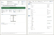
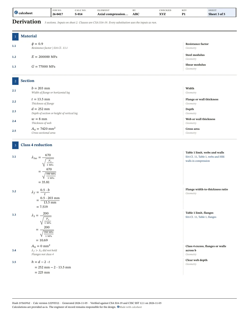
Sheet 1 and the first sheet of the working of the PDF report, at the declared values with a sample title block. First report free, then a free sign-in.
Show the two sheets
Sheet 1 of the Axial compression of a W section or HSS report: title block, verdict, checks and figures
Sheet 1: title block, verdict, checks, figures · full size
The first sheet of the working in the Axial compression of a W section or HSS report: each step with its clause
The working: each step with its clause · full size

Questions

Which n does an HSS take in S16 Cl. 13.3.1.1?

1.34, a class C cold-formed section. A stress-relieved class H HSS would take 2.24 and a higher resistance.

Where do A_0, r_x, r_y, J and C_w come from?

The CISC Structural Section Tables, SST 12.1: area, radii, J and C_w, and the element dimensions.

Revision history

After an independent checker's review: added slenderness checks of KL/r against 200 on each axis (Cl. 10.4.2.1), an HSS no longer takes torsional buckling (Cl. 13.3.1.2 Note 2), the class 4 reduction cites Cl. 13.3.4 a), and the twist-restraint assumption is listed as not checked
ValueWasNowUnit
slender_x_ok
slender_y_ok
fix(units,examples): zero keeps its unit, zero cope, shear tab rules
ValueWasNowUnit
A_b0 \mathrm{m}^{2}0mm2\mathrm{mm}^{2}
A_d0 \mathrm{m}^{2}0mm2\mathrm{mm}^{2}