 calcsheet
 Tension development length and lap splice (A23.3-19)
CSA A23.3-19Verified against CSA A23.3-19: 18 formulas and 12 clauses compared with the code text, 3 rows from definitions, statics and tables
Development length and Class A and B lap splice length of a straight reinforcing bar in tension, to CSA A23.3-19 Cl. 12.2 and 12.15. Calculate the development length of a straight reinforcing bar in tension per CSA A23.3-19 Cl. 12.2, the edition NBC 2020 references, and its Class A and B lap splices per Cl. 12.15.1. The calc works out the general expression of Eq. 12.1, 1.15 k1 k2 k3 k4 / (d_cs + K_tr) f_y / sqrt(f'c) A_b with K_tr = A_tr f_yt / (10.5 s n) and (d_cs + K_tr) not more than 2.5 d_b, and, where the clear cover and spacing of Cl. 12.2.3 allow it, the simplified expression of Table 12.1, and takes the shorter, since Cl. 12.2.1 permits either. The four modification factors of Cl. 12.2.4 are each shown with the condition that sets them, and l_d is never less than 300 mm. Bundled bars take the equivalent diameter of Cl. 7.4.2.4 in the cover and spacing tests of Cl. 12.2.3, Table 12.1 and the epoxy factor. The same calc to CSA A23.3-24 is the Tension development length and lap splice page.
First report free, then a free sign-in
Given
Jump to resultsType any value, everything below recomputes. Hover or tap a symbol to trace it.
Resume your last case ()? Load it
This printed copy omits the derivation. The full report, with every step, is the PDF at https://calc.struct.work/calc/development-length-tension-a23.3-19.pdf.
Results
Development length required in tension, in , for every bar size against concrete compressive strength, with the other inputs as entered. Bold: 15M at , whose derivation is below.
| Bar size | ||||||
|---|---|---|---|---|---|---|
| 10M | 300a | 300a | 300a | 300a | 300a | 300a |
| 15M | 368 | 335.9 | 311 | 300a | 300a | 300a |
| 20M | 452.9 | 413.5 | 382.8 | 358.1 | 337.6 | 320.3 |
| 25M | 730.2 | 666.5 | 617.1 | 577.2 | 544.2 | 516.3 |
| 30M | 861.5 | 786.5 | 728.1 | 681.1 | 642.2 | 609.2 |
| 35M | 1105 | 1009 | 934 | 873.7 | 823.7 | 781.5 |
| 45M | 1582 | 1444 | 1337 | 1250 | 1179 | 1118 |
| 55M | 2457 | 2243 | 2077 | 1943 | 1832 | 1738 |
- Single-bar at the 300 mm minimum of Cl. 12.2.1, before the bundle factor
Class A tension lap splice, Cl. 12.15.1 a), in , for every bar size against concrete compressive strength, with the other inputs as entered. Bold: 15M at , whose derivation is below.
| Bar size | ||||||
|---|---|---|---|---|---|---|
| 10M | 300a | 300a | 300a | 300a | 300a | 300a |
| 15M | 368 | 335.9 | 311 | 300a | 300a | 300a |
| 20M | 452.9 | 413.5 | 382.8 | 358.1 | 337.6 | 320.3 |
| 25M | 730.2 | 666.5 | 617.1 | 577.2 | 544.2 | 516.3 |
| 30M | 861.5 | 786.5 | 728.1 | 681.1 | 642.2 | 609.2 |
| 35M | 1105 | 1009 | 934 | 873.7 | 823.7 | 781.5 |
| 45M | -b | -b | -b | -b | -b | -b |
| 55M | -b | -b | -b | -b | -b | -b |
- Splice at the 300 mm minimum of Cl. 12.2.1 and 12.15.1, before the lap class and bundle factors
- No tension lap splice of a bar larger than 35M, Cl. 12.14.2.1
Class B tension lap splice, Cl. 12.15.1 b), in , for every bar size against concrete compressive strength, with the other inputs as entered. Bold: 15M at , whose derivation is below.
| Bar size | ||||||
|---|---|---|---|---|---|---|
| 10M | 390a | 390a | 390a | 390a | 390a | 390a |
| 15M | 478.4 | 436.7 | 404.3 | 390a | 390a | 390a |
| 20M | 588.8 | 537.5 | 497.6 | 465.5 | 438.9 | 416.3 |
| 25M | 949.2 | 866.5 | 802.2 | 750.4 | 707.5 | 671.2 |
| 30M | 1120 | 1022 | 946.6 | 885.4 | 834.8 | 792 |
| 35M | 1437 | 1312 | 1214 | 1136 | 1071 | 1016 |
| 45M | -b | -b | -b | -b | -b | -b |
| 55M | -b | -b | -b | -b | -b | -b |
- Splice at the 300 mm minimum of Cl. 12.2.1 and 12.15.1, before the lap class and bundle factors
- No tension lap splice of a bar larger than 35M, Cl. 12.14.2.1
Also worth checking
- Which lap splice class applies, Cl. 12.15.2, and for column bars in tension Cl. 12.17.3.2 and 12.17.3.3 by the bar stress: both Class A and Class B lengths are given, and the area ratio, the fraction spliced and the bar stress are not checked
- Laps between bars of different sizes, Cl. 12.15.1, and welded splices or mechanical connections, Cl. 12.15.3 and 12.15.4
- Splices in tension tie members must be full welded or full mechanical, staggered by 800 mm, Cl. 12.15.5
- Where flexural bars may stop or must extend past the point of maximum stress, Cl. 12.10 to 12.12
- The excess reinforcement ratio is taken as entered; that the member is flexural, and the exceptions of Cl. 12.2.5 (development for f_y specifically required, or Cl. 21 design), are not checked
- Clear cover and clear spacing are taken as entered; whether they meet the cover and spacing the member needs is not checked
- For a bundle, d_cs and its 2.5 d_b cap in Eq. 12.1 are taken on a single bar of the bundle, the longer reading; Cl. 7.4.2.4 is applied only to the cover and spacing limits
- For a single bar (n = 1) the clear spacing still enters d_cs (Cl. 3.2), the epoxy factor and Cl. 12.2.3; enter the clear distance to the nearest parallel bar, or a large value where there is none
- Whether the ties or stirrups ticked as minimum meet Cl. 7.6.5 or Cl. 11.2.8.2 within l_d is not checked
- Transverse steel is taken as entered: that A_tr lies within s and crosses the potential plane of splitting, and that s is the largest spacing within l_d, is not checked (Cl. 3.2)
- Lap splices of 45M and 55M bars are not given: Cl. 12.14.2.1 does not permit lap splices of bars larger than 35M in tension
- Transverse spacing of lapped bars in flexural members, not more than one-fifth of the lap length or 150 mm, Cl. 12.14.2.3
- Individual splices within a bundle must not overlap, Cl. 12.14.2.2
- The bundle limits of Cl. 7.4.2.1 and 7.4.2.2, and bars of a bundle cut off within the span at least 40 bar diameters apart, Cl. 7.4.2.3
- Hooked and mechanically anchored bars, Cl. 12.5 and 12.6
- Seismic requirements for development and lap splices, Clause 21: the Cl. 12.2.5 reduction does not apply to reinforcement resisting earthquake forces (Cl. 21.2.7.2.1), lap splices are restricted in ductile members and walls (Cl. 21.2.7.2.2, including laps of 1.5 l_d), and bars anchored in joints follow Cl. 21.3.3.5
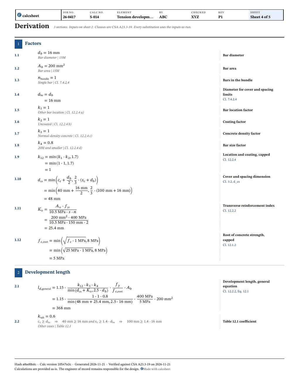
Derivation
and
The bar is 35M or smaller, so its Class A and B tension laps are given, Cl. 12.14.2.1.
Report
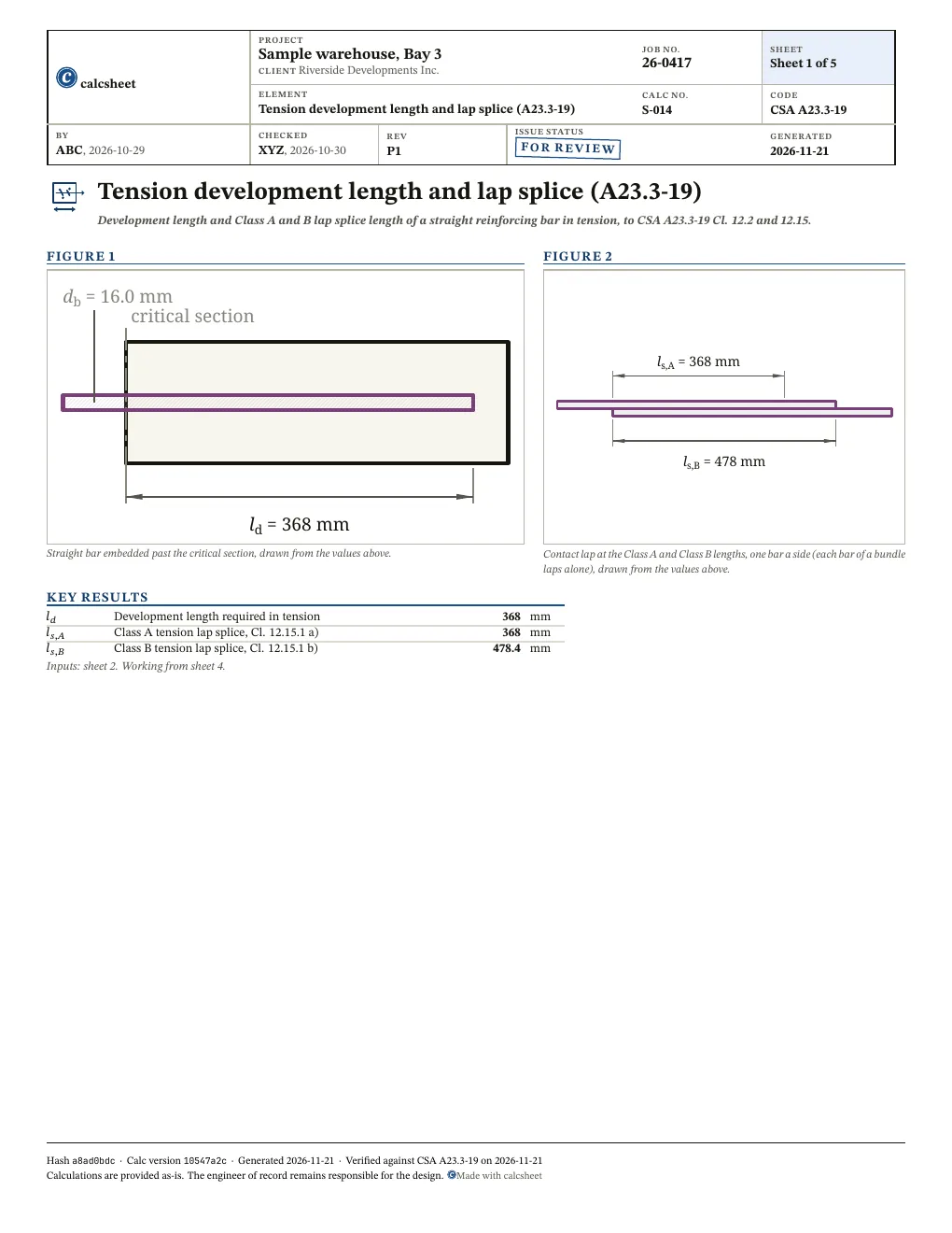
Sheet 1 and the first sheet of the working of the PDF report, at the declared values with a sample title block. First report free, then a free sign-in.
Questions
Should I use CSA A23.3-19 or A23.3-24?
Use the edition your building code references. NBC 2020 references CSA A23.3-19. A provincial code may differ, so check the one that governs the project. The Edition select on the code line opens the same case under the other edition.
Why is l_d the shorter of l_d_general and l_d_simplified?
Cl. 12.2.1 lets l_d come from either Eq. 12.1 of Cl. 12.2.2 or Table 12.1 of Cl. 12.2.3. The table applies only with clear cover of at least d_b and clear spacing of at least 1.4 d_b, taken on the equivalent diameter of Cl. 7.4.2.4 for a bundle. Where it applies the calc takes the shorter, and l_d is never less than 300 mm.
What is K_tr, and why does it need f_yt?
Cl. 12.2.2 takes K_tr = A_tr f_yt / (10.5 s n), where f_yt is the yield strength of the transverse reinforcement crossing the plane of splitting. The term d_cs + K_tr is not taken greater than 2.5 d_b, so heavy ties stop shortening l_d at that point.
Why are l_s_A and l_s_B not given for 45M and 55M bars?
Cl. 12.14.2.1 permits no lap splice of a bar larger than 35M except as Cl. 12.16.2 and 15.9.2.4 allow, and both are compression laps. Below that, Cl. 12.15.1 gives Class A as 1.0 l_d and Class B as 1.3 l_d, without the excess steel factor of Cl. 12.2.5.