ConcreteRC bracket and corbel

Strut-and-tie design of a reinforced concrete bracket or corbel to CSA A23.3-24. Design reinforced concrete brackets and corbels using the strut-and-tie method per CSA A23.3-24 Clause 11.6. The calculator models the internal load path with concrete compression struts and steel tension ties, then determines required reinforcement and checks the bearing plate, the struts and nodes, the ties and shear friction at the column face. Input corbel geometry, applied loads, and material properties for a complete design check.

CA$4.00 for this report, or Pro

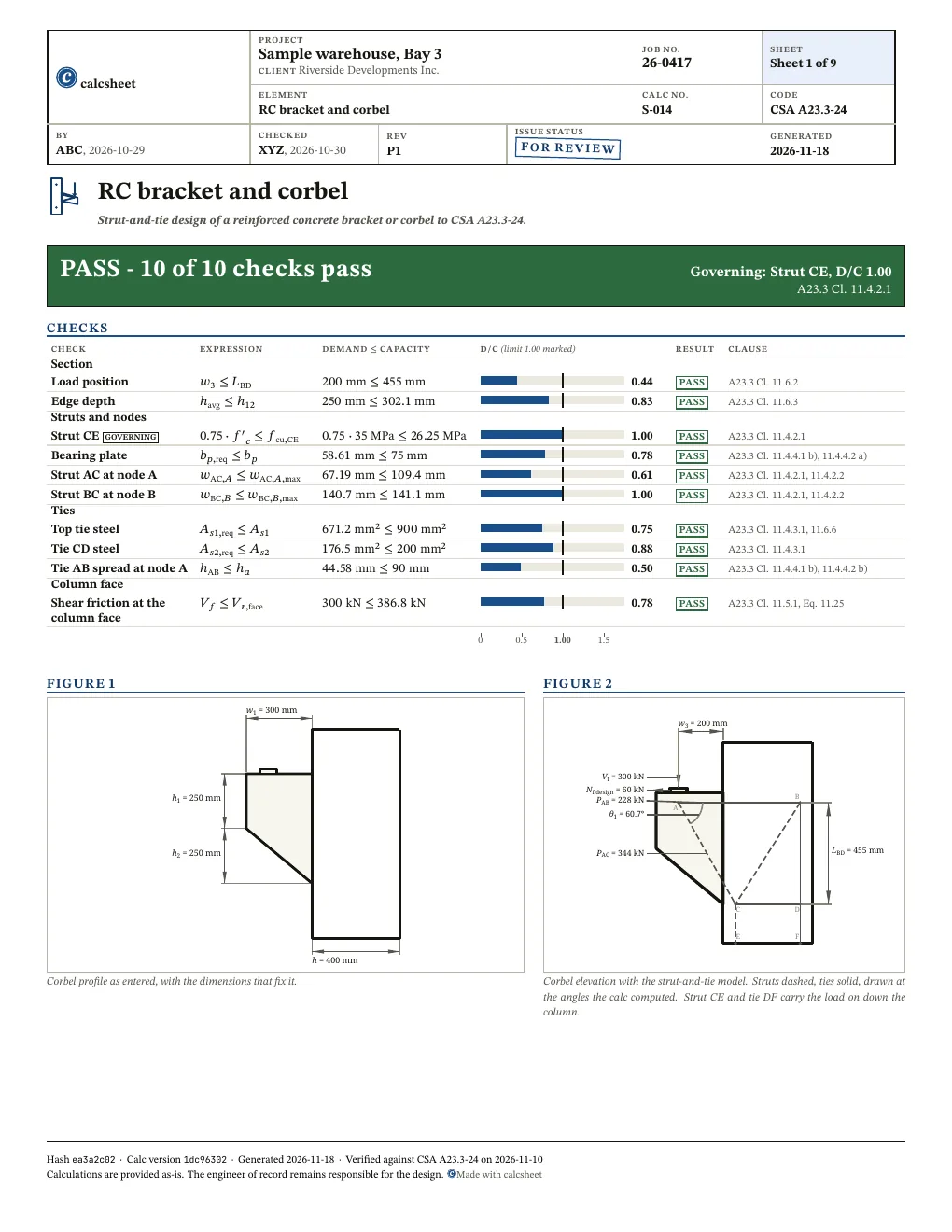
PASS Governing: Strut CE, D/C 1.00, A23.3 Cl. 11.4.2.110 of 10 checks below pass

w1 = 300 mm h1 = 250 mm h2 = 250 mm h = 400 mm
Corbel profile as entered, with the dimensions that fix it.
Vf = 300 kN Nf,design = 60 kN A B C D E F θ1 = 60.7° PAC = 344 kN PAB = 228 kN w3 = 200 mm LBD = 455 mm
Corbel elevation with the strut-and-tie model. Struts dashed, ties solid, drawn at the angles the calc computed. Strut CE and tie DF carry the load on down the column.

Given

Jump to results

Type any value, everything below recomputes. Hover or tap a symbol to trace it.

Loads
changed from the declared value VfV_{f} kN\mathrm{kN}10-85,000
changed from the declared value NfN_{f} kN\mathrm{kN}0-5,000
Column
changed from the declared value bb mm\mathrm{mm}100-2,000
changed from the declared value hh mm\mathrm{mm}100-2,000
changed from the declared value w2w_{2} mm\mathrm{mm}100-2,000
Corbel
changed from the declared value h1h_{1} mm\mathrm{mm}50-1,000
changed from the declared value h2h_{2} mm\mathrm{mm}0-1,000
changed from the declared value w1w_{1} mm\mathrm{mm}50-1,000
changed from the declared value w4w_{4} mm\mathrm{mm}50-1,000
changed from the declared value w3w_{3} mm\mathrm{mm}20-1,000
changed from the declared value
Bearing plate
changed from the declared value LpL_{p} mm\mathrm{mm}50-1,000
changed from the declared value bpb_{p} mm\mathrm{mm}25-500
Materials
changed from the declared value fyf_{y} MPa\mathrm{MPa}200-500
changed from the declared value f′c{f'}_{c} MPa\mathrm{MPa}20-80
changed from the declared value ϕc\phi_{c} 0.65-0.7
Reinforcement
changed from the declared value As1A_{s1} mm2\mathrm{mm}^{2}100-20,000
changed from the declared value As2A_{s2} mm2\mathrm{mm}^{2}100-20,000
changed from the declared value a1a_{1} mm\mathrm{mm}20-200
changed from the declared value a2a_{2} mm\mathrm{mm}20-200

Title block

Optional. Printed in the title block of the PDF.

Checks

All 10 checks pass. Largest D/C 1.00, Strut CE.

Show all 10 checks

! marks a check that passes with D/C at or above 0.95: close to its limit. The band is a site convention, not a code limit.

Section

Check D/C Utilisation Result
Load positionA23.3 Cl. 11.6.2w3≤LBD⇒200 mm≤455 mm\htmlClass{sym-w3}{w_{3}} \leq \htmlClass{sym-L_BD}{L_{\mathrm{BD}}} \quad \Rightarrow \quad \htmlClass{sym-w3}{200\ \mathrm{mm}} \leq \htmlClass{sym-L_BD}{455\ \mathrm{mm}} 0.44 PASS
Edge depthA23.3 Cl. 11.6.3havg≤h12⇒250 mm≤302.1 mm\htmlClass{sym-h_avg}{h_{\mathrm{avg}}} \leq \htmlClass{sym-h12}{h_{12}} \quad \Rightarrow \quad \htmlClass{sym-h_avg}{250\ \mathrm{mm}} \leq \htmlClass{sym-h12}{302.1\ \mathrm{mm}} 0.83 PASS

Struts and nodes

Check D/C Utilisation Result
Strut CEA23.3 Cl. 11.4.2.10.75⋅f′c≤fcu,CE⇒0.75⋅35 MPa≤26.25 MPa0.75 \cdot \htmlClass{sym-f_prime_c}{{f'}_{c}} \leq \htmlClass{sym-f_cu_CE}{f_{\mathrm{cu},\mathrm{CE}}} \quad \Rightarrow \quad 0.75 \cdot \htmlClass{sym-f_prime_c}{35\ \mathrm{MPa}} \leq \htmlClass{sym-f_cu_CE}{26.25\ \mathrm{MPa}} 1.00 PASS
Bearing plateA23.3 Cl. 11.4.4.1 b), 11.4.4.2 a)bp,req≤bp⇒58.61 mm≤75 mm\htmlClass{sym-b_p_req}{b_{p,\mathrm{req}}} \leq \htmlClass{sym-b_p}{b_{p}} \quad \Rightarrow \quad \htmlClass{sym-b_p_req}{58.61\ \mathrm{mm}} \leq \htmlClass{sym-b_p}{75\ \mathrm{mm}} 0.78 PASS
Strut AC at node AA23.3 Cl. 11.4.2.1, 11.4.2.2wAC,A≤wAC,A,max⇒67.19 mm≤109.4 mm\htmlClass{sym-w_AC_A}{w_{\mathrm{AC},A}} \leq \htmlClass{sym-w_AC_A_max}{w_{\mathrm{AC},A,\mathrm{max}}} \quad \Rightarrow \quad \htmlClass{sym-w_AC_A}{67.19\ \mathrm{mm}} \leq \htmlClass{sym-w_AC_A_max}{109.4\ \mathrm{mm}} 0.61 PASS
Strut BC at node BA23.3 Cl. 11.4.2.1, 11.4.2.2wBC,B≤wBC,B,max⇒140.7 mm≤141.1 mm\htmlClass{sym-w_BC_B}{w_{\mathrm{BC},B}} \leq \htmlClass{sym-w_BC_B_max}{w_{\mathrm{BC},B,\mathrm{max}}} \quad \Rightarrow \quad \htmlClass{sym-w_BC_B}{140.7\ \mathrm{mm}} \leq \htmlClass{sym-w_BC_B_max}{141.1\ \mathrm{mm}} 1.00 PASS

Ties

Check D/C Utilisation Result
Top tie steelA23.3 Cl. 11.4.3.1, 11.6.6As1,req≤As1⇒671.2 mm2≤900 mm2\htmlClass{sym-A_s1_req}{A_{s1,\mathrm{req}}} \leq \htmlClass{sym-A_s1}{A_{s1}} \quad \Rightarrow \quad \htmlClass{sym-A_s1_req}{671.2\ \mathrm{mm}^{2}} \leq \htmlClass{sym-A_s1}{900\ \mathrm{mm}^{2}} 0.75 PASS
Tie CD steelA23.3 Cl. 11.4.3.1As2,req≤As2⇒176.5 mm2≤200 mm2\htmlClass{sym-A_s2_req}{A_{s2,\mathrm{req}}} \leq \htmlClass{sym-A_s2}{A_{s2}} \quad \Rightarrow \quad \htmlClass{sym-A_s2_req}{176.5\ \mathrm{mm}^{2}} \leq \htmlClass{sym-A_s2}{200\ \mathrm{mm}^{2}} 0.88 PASS
Tie AB spread at node AA23.3 Cl. 11.4.4.1 b), 11.4.4.2 b)hAB≤ha⇒44.58 mm≤90 mm\htmlClass{sym-h_AB}{h_{\mathrm{AB}}} \leq \htmlClass{sym-h_a}{h_{a}} \quad \Rightarrow \quad \htmlClass{sym-h_AB}{44.58\ \mathrm{mm}} \leq \htmlClass{sym-h_a}{90\ \mathrm{mm}} 0.50 PASS

Column face

Check D/C Utilisation Result
Shear friction at the column faceA23.3 Cl. 11.5.1, Eq. 11.25Vf≤Vr,face⇒300 kN≤386.8 kN\htmlClass{sym-V_f}{V_{f}} \leq \htmlClass{sym-V_r_face}{V_{r,\mathrm{face}}} \quad \Rightarrow \quad \htmlClass{sym-V_f}{300\ \mathrm{kN}} \leq \htmlClass{sym-V_r_face}{386.8\ \mathrm{kN}} 0.78 PASS

Results

Concrete

Quantity Description Value Unit
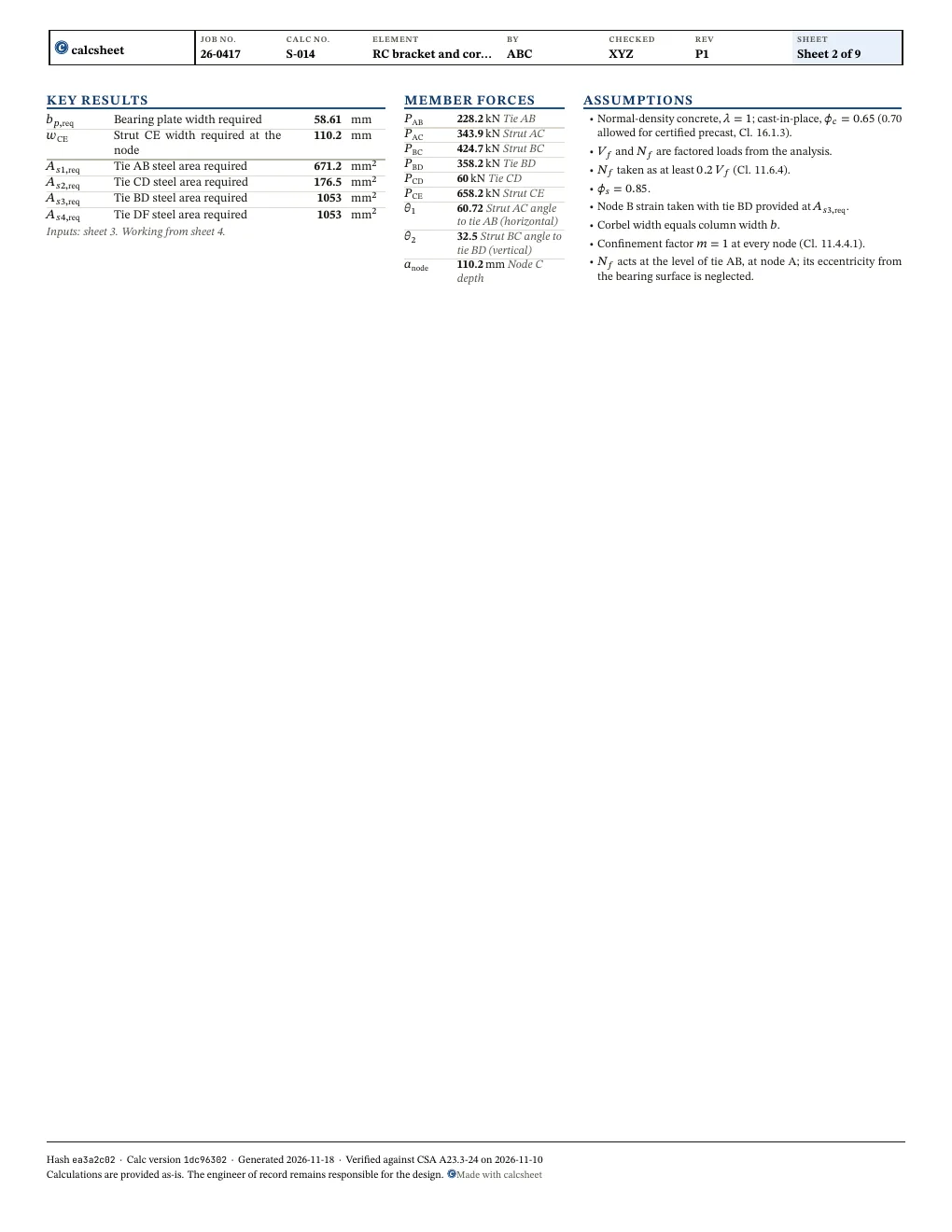
bp,req\htmlClass{sym-b_p_req}{b_{p,\mathrm{req}}} Bearing plate width required 58.61 mm\mathrm{mm}
wCE\htmlClass{sym-w_CE}{w_{\mathrm{CE}}} Strut CE width required at the node 110.2 mm\mathrm{mm}

Tie steel

Quantity Description Value Unit
As1,req\htmlClass{sym-A_s1_req}{A_{s1,\mathrm{req}}} Tie AB steel area required 671.2 mm2\mathrm{mm}^{2}
As2,req\htmlClass{sym-A_s2_req}{A_{s2,\mathrm{req}}} Tie CD steel area required 176.5 mm2\mathrm{mm}^{2}
As3,req\htmlClass{sym-A_s3_req}{A_{s3,\mathrm{req}}} Tie BD steel area required 1053 mm2\mathrm{mm}^{2}
As4,req\htmlClass{sym-A_s4_req}{A_{s4,\mathrm{req}}} Tie DF steel area required 1053 mm2\mathrm{mm}^{2}

Member forces

Quantity Description Value Unit
PAB\htmlClass{sym-P_AB}{P_{\mathrm{AB}}} Tie AB 228.2 kN\mathrm{kN}
PAC\htmlClass{sym-P_AC}{P_{\mathrm{AC}}} Strut AC 343.9 kN\mathrm{kN}
PBC\htmlClass{sym-P_BC}{P_{\mathrm{BC}}} Strut BC 424.7 kN\mathrm{kN}
PBD\htmlClass{sym-P_BD}{P_{\mathrm{BD}}} Tie BD 358.2 kN\mathrm{kN}
PCD\htmlClass{sym-P_CD}{P_{\mathrm{CD}}} Tie CD 60 kN\mathrm{kN}
PCE\htmlClass{sym-P_CE}{P_{\mathrm{CE}}} Strut CE 658.2 kN\mathrm{kN}
θ1\htmlClass{sym-theta1}{\theta_{1}} Strut AC angle to tie AB (horizontal) 60.72
θ2\htmlClass{sym-theta2}{\theta_{2}} Strut BC angle to tie BD (vertical) 32.5governs
anode\htmlClass{sym-a_node}{a_{\mathrm{node}}} Node C depth 110.2 mm\mathrm{mm}
Also worth checking
  • The steel provided in ties BD and DF, in the column: their required areas are computed, not compared. The node B width check takes tie BD at A_s3,req, so it holds only with at least that much steel
  • The widths of struts AC and BC at node C (Cl. 11.4.1.1, 11.4.2.2): w_AC_C and w_BC_C are computed, not compared. Figure 11.5 c), a strut anchored by a bearing and a strut, is the nearest code form, with strut CE as the bearing, but it needs the depth of tie CD below the corbel, which is not an input
  • The closed ties over two thirds of the corbel depth: their minimum area is sized, not compared with a bar layout
  • Anchorage of every tie (Cl. 11.4.3.2, 11.4.3.3, 11.6.7), and of A_s1 each side of the column face for shear friction (Cl. 11.5.6), bar spacing and cover
  • Whether the plate stays on the straight part of tie AB (Cl. 11.6.8): only a plate past the tip is refused
  • Reinforcement for bursting, splitting and spalling under the plate (Cl. 10.8.2)
  • The column and the section below the corbel, and the bearing pad material

Derivation

1.1Steel modulus
Es=200000 MPa(Steel modulus | CSA A23.3 Cl. 8.5.3.1)\begin{aligned} \htmlClass{sym-E_s}{E_{s}} &= 200000\ \mathrm{MPa} \quad \left(\text{Steel modulus | CSA A23.3 Cl. 8.5.3.1}\right) \end{aligned}
1.2Minimum horizontal load

A23.3 Cl. 11.6.4

Nf,min=0.2⋅Vf=0.2⋅300 kN=60 kN\begin{aligned} \htmlClass{sym-N_f_min}{N_{f,\mathrm{min}}} &= 0.2 \cdot \htmlClass{sym-V_f}{V_{f}} \\ &= 0.2 \cdot \htmlClass{sym-V_f}{300\ \mathrm{kN}} \\ &= 60\ \mathrm{kN} \end{aligned}
1.3Design horizontal load

A23.3 Cl. 11.6.4

Nf,design=max⁡(Nf,Nf,min)=max⁡(0 kN,60 kN)=60 kN\begin{aligned} \htmlClass{sym-N_f_design}{N_{f,\mathrm{design}}} &= \max\left(\htmlClass{sym-N_f}{N_{f}}, \htmlClass{sym-N_f_min}{N_{f,\mathrm{min}}}\right) \\ &= \max\left(\htmlClass{sym-N_f}{0\ \mathrm{kN}}, \htmlClass{sym-N_f_min}{60\ \mathrm{kN}}\right) \\ &= 60\ \mathrm{kN} \end{aligned}
2.1Plate width required

A23.3 Cl. 11.4.4.1 b), 11.4.4.2 a)

bp,req=VfLp⋅0.75⋅ϕc⋅f′c=300 kN300 mm⋅0.75⋅0.65⋅35 MPa=58.61 mm\begin{aligned} \htmlClass{sym-b_p_req}{b_{p,\mathrm{req}}} &= \frac{\htmlClass{sym-V_f}{V_{f}}}{\htmlClass{sym-L_p}{L_{p}} \cdot 0.75 \cdot \htmlClass{sym-phi_c}{\phi_{c}} \cdot \htmlClass{sym-f_prime_c}{{f'}_{c}}} \\ &= \frac{\htmlClass{sym-V_f}{300\ \mathrm{kN}}}{\htmlClass{sym-L_p}{300\ \mathrm{mm}} \cdot 0.75 \cdot \htmlClass{sym-phi_c}{0.65} \cdot \htmlClass{sym-f_prime_c}{35\ \mathrm{MPa}}} \\ &= 58.61\ \mathrm{mm} \end{aligned}

Node A is bounded by the plate and strut AC and anchors tie AB, so Cl. 11.4.4.2 a) holds the bearing stress to the 0.75 ϕcfc′0.75\,\phi_{c} f'_{c} node limit of Cl. 11.4.4.1 b), taken with m=1m = 1. It governs over the 0.85 ϕcfc′0.85\,\phi_{c} f'_{c} bearing limit of Cl. 10.8.1.

3.1Tie BD length, lever arm of N_f about D
LBD=h1+h2−a1=250 mm+250 mm−45 mm=455 mm\begin{aligned} \htmlClass{sym-L_BD}{L_{\mathrm{BD}}} &= \htmlClass{sym-h1}{h_{1}} + \htmlClass{sym-h2}{h_{2}} - \htmlClass{sym-a1}{a_{1}} \\ &= \htmlClass{sym-h1}{250\ \mathrm{mm}} + \htmlClass{sym-h2}{250\ \mathrm{mm}} - \htmlClass{sym-a1}{45\ \mathrm{mm}} \\ &= 455\ \mathrm{mm} \end{aligned}
3.2Plate's outer edge from column face
xp=w3+bp2=200 mm+75 mm2=237.5 mm\begin{aligned} \htmlClass{sym-x_p}{x_{p}} &= \htmlClass{sym-w3}{w_{3}} + \frac{\htmlClass{sym-b_p}{b_{p}}}{2} \\ &= \htmlClass{sym-w3}{200\ \mathrm{mm}} + \frac{\htmlClass{sym-b_p}{75\ \mathrm{mm}}}{2} \\ &= 237.5\ \mathrm{mm} \end{aligned}

w1>xp⇒300 mm>237.5 mmw_{1} > x_{p} \quad \Rightarrow \quad 300\ \mathrm{mm} > 237.5\ \mathrm{mm}

xp≤w4⇒237.5 mm≤300 mmx_{p} \leq w_{4} \quad \Rightarrow \quad 237.5\ \mathrm{mm} \leq 300\ \mathrm{mm}

3.3Depth at the plate's outer edge
h12=h1+h2⋅(w4−xp)w4=250 mm+250 mm⋅(300 mm−237.5 mm)300 mm=302.1 mm\begin{aligned} \htmlClass{sym-h12}{h_{12}} &= \htmlClass{sym-h1}{h_{1}} + \frac{\htmlClass{sym-h2}{h_{2}} \cdot \left(\htmlClass{sym-w4}{w_{4}} - \htmlClass{sym-x_p}{x_{p}}\right)}{\htmlClass{sym-w4}{w_{4}}} \\ &= \htmlClass{sym-h1}{250\ \mathrm{mm}} + \frac{\htmlClass{sym-h2}{250\ \mathrm{mm}} \cdot \left(\htmlClass{sym-w4}{300\ \mathrm{mm}} - \htmlClass{sym-x_p}{237.5\ \mathrm{mm}}\right)}{\htmlClass{sym-w4}{300\ \mathrm{mm}}} \\ &= 302.1\ \mathrm{mm} \end{aligned}

Cl. 11.6.3 compares the depth under the plate's outer edge, xpx_{p} from the column face, with half the depth at the face, havgh_{\mathrm{avg}}.

3.4Half the depth at the column face
havg=h1+h22=250 mm+250 mm2=250 mm\begin{aligned} \htmlClass{sym-h_avg}{h_{\mathrm{avg}}} &= \frac{\htmlClass{sym-h1}{h_{1}} + \htmlClass{sym-h2}{h_{2}}}{2} \\ &= \frac{\htmlClass{sym-h1}{250\ \mathrm{mm}} + \htmlClass{sym-h2}{250\ \mathrm{mm}}}{2} \\ &= 250\ \mathrm{mm} \end{aligned}
4.1Tie AB length, lever arm of V_f about D
LAB=w3+h−a2=200 mm+400 mm−55 mm=545 mm\begin{aligned} \htmlClass{sym-L_AB}{L_{\mathrm{AB}}} &= \htmlClass{sym-w3}{w_{3}} + \htmlClass{sym-h}{h} - \htmlClass{sym-a2}{a_{2}} \\ &= \htmlClass{sym-w3}{200\ \mathrm{mm}} + \htmlClass{sym-h}{400\ \mathrm{mm}} - \htmlClass{sym-a2}{55\ \mathrm{mm}} \\ &= 545\ \mathrm{mm} \end{aligned}
4.2Moment of the loads about node D
MD=Nf,design⋅LBD+Vf⋅LAB=60 kN⋅455 mm+300 kN⋅545 mm=190.8 kN⋅m\begin{aligned} \htmlClass{sym-M_D}{M_{D}} &= \htmlClass{sym-N_f_design}{N_{f,\mathrm{design}}} \cdot \htmlClass{sym-L_BD}{L_{\mathrm{BD}}} + \htmlClass{sym-V_f}{V_{f}} \cdot \htmlClass{sym-L_AB}{L_{\mathrm{AB}}} \\ &= \htmlClass{sym-N_f_design}{60\ \mathrm{kN}} \cdot \htmlClass{sym-L_BD}{455\ \mathrm{mm}} + \htmlClass{sym-V_f}{300\ \mathrm{kN}} \cdot \htmlClass{sym-L_AB}{545\ \mathrm{mm}} \\ &= 190.8\ \mathrm{kN} \cdot \mathrm{m} \end{aligned}
4.3Node C stress limit

A23.3 Cl. 11.4.4.1 b)

fnode,C=0.75⋅ϕc⋅f′c=0.75⋅0.65⋅35 MPa=17.06 MPa\begin{aligned} \htmlClass{sym-f_node_C}{f_{\mathrm{node},C}} &= 0.75 \cdot \htmlClass{sym-phi_c}{\phi_{c}} \cdot \htmlClass{sym-f_prime_c}{{f'}_{c}} \\ &= 0.75 \cdot \htmlClass{sym-phi_c}{0.65} \cdot \htmlClass{sym-f_prime_c}{35\ \mathrm{MPa}} \\ &= 17.06\ \mathrm{MPa} \end{aligned}
4.4Node C depth
anode=h−a2−(h−a2)2−2⋅MDfnode,C⋅b=400 mm−55 mm−(400 mm−55 mm)2−2⋅190.8 kN⋅m17.06 MPa⋅350 mm=110.2 mm\begin{aligned} \htmlClass{sym-a_node}{a_{\mathrm{node}}} &= \htmlClass{sym-h}{h} - \htmlClass{sym-a2}{a_{2}} - \sqrt{\left(\htmlClass{sym-h}{h} - \htmlClass{sym-a2}{a_{2}}\right)^{2} - \frac{2 \cdot \htmlClass{sym-M_D}{M_{D}}}{\htmlClass{sym-f_node_C}{f_{\mathrm{node},C}} \cdot \htmlClass{sym-b}{b}}} \\ &= \htmlClass{sym-h}{400\ \mathrm{mm}} - \htmlClass{sym-a2}{55\ \mathrm{mm}} - \sqrt{\left(\htmlClass{sym-h}{400\ \mathrm{mm}} - \htmlClass{sym-a2}{55\ \mathrm{mm}}\right)^{2} - \frac{2 \cdot \htmlClass{sym-M_D}{190.8\ \mathrm{kN} \cdot \mathrm{m}}}{\htmlClass{sym-f_node_C}{17.06\ \mathrm{MPa}} \cdot \htmlClass{sym-b}{350\ \mathrm{mm}}}} \\ &= 110.2\ \mathrm{mm} \end{aligned}

Root of fnode,C b a (h−a2−a/2)=MDf_{\mathrm{node},C}\, b\, a\,(h - a_{2} - a/2) = M_{D}, the moment of strut CE about D equal to the moment of the loads.

4.5Tie CD length, lever arm of strut CE about D
LCD=h−a2−anode2=400 mm−55 mm−110.2 mm2=289.9 mm\begin{aligned} \htmlClass{sym-L_CD}{L_{\mathrm{CD}}} &= \htmlClass{sym-h}{h} - \htmlClass{sym-a2}{a_{2}} - \frac{\htmlClass{sym-a_node}{a_{\mathrm{node}}}}{2} \\ &= \htmlClass{sym-h}{400\ \mathrm{mm}} - \htmlClass{sym-a2}{55\ \mathrm{mm}} - \frac{\htmlClass{sym-a_node}{110.2\ \mathrm{mm}}}{2} \\ &= 289.9\ \mathrm{mm} \end{aligned}
4.6Strut CE force
PCE=MDLCD=190.8 kN⋅m289.9 mm=658.2 kN\begin{aligned} \htmlClass{sym-P_CE}{P_{\mathrm{CE}}} &= \frac{\htmlClass{sym-M_D}{M_{D}}}{\htmlClass{sym-L_CD}{L_{\mathrm{CD}}}} \\ &= \frac{\htmlClass{sym-M_D}{190.8\ \mathrm{kN} \cdot \mathrm{m}}}{\htmlClass{sym-L_CD}{289.9\ \mathrm{mm}}} \\ &= 658.2\ \mathrm{kN} \end{aligned}
θ1,rad=arctan⁡(LBDLAB−LCD)=arctan⁡(455 mm545 mm−289.9 mm)=1.06\begin{aligned} \htmlClass{sym-theta1_rad}{\theta_{1,\mathrm{rad}}} &= \arctan\left(\frac{\htmlClass{sym-L_BD}{L_{\mathrm{BD}}}}{\htmlClass{sym-L_AB}{L_{\mathrm{AB}}} - \htmlClass{sym-L_CD}{L_{\mathrm{CD}}}}\right) \\ &= \arctan\left(\frac{\htmlClass{sym-L_BD}{455\ \mathrm{mm}}}{\htmlClass{sym-L_AB}{545\ \mathrm{mm}} - \htmlClass{sym-L_CD}{289.9\ \mathrm{mm}}}\right) \\ &= 1.06 \end{aligned}
5.1Strut AC angle to tie AB
θ1=degrees⁡(θ1,rad)=degrees⁡(1.06)=60.72\begin{aligned} \htmlClass{sym-theta1}{\theta_{1}} &= \operatorname{degrees}\left(\htmlClass{sym-theta1_rad}{\theta_{1,\mathrm{rad}}}\right) \\ &= \operatorname{degrees}\left(\htmlClass{sym-theta1_rad}{1.06}\right) \\ &= 60.72 \end{aligned}
5.2Strut AC force
PAC=Vfsin⁡(θ1,rad)=300 kNsin⁡(1.06)=343.9 kN\begin{aligned} \htmlClass{sym-P_AC}{P_{\mathrm{AC}}} &= \frac{\htmlClass{sym-V_f}{V_{f}}}{\sin\left(\htmlClass{sym-theta1_rad}{\theta_{1,\mathrm{rad}}}\right)} \\ &= \frac{\htmlClass{sym-V_f}{300\ \mathrm{kN}}}{\sin\left(\htmlClass{sym-theta1_rad}{1.06}\right)} \\ &= 343.9\ \mathrm{kN} \end{aligned}
5.3Tie AB force
PAB=Vftan⁡(θ1,rad)+Nf,design=300 kNtan⁡(1.06)+60 kN=228.2 kN\begin{aligned} \htmlClass{sym-P_AB}{P_{\mathrm{AB}}} &= \frac{\htmlClass{sym-V_f}{V_{f}}}{\tan\left(\htmlClass{sym-theta1_rad}{\theta_{1,\mathrm{rad}}}\right)} + \htmlClass{sym-N_f_design}{N_{f,\mathrm{design}}} \\ &= \frac{\htmlClass{sym-V_f}{300\ \mathrm{kN}}}{\tan\left(\htmlClass{sym-theta1_rad}{1.06}\right)} + \htmlClass{sym-N_f_design}{60\ \mathrm{kN}} \\ &= 228.2\ \mathrm{kN} \end{aligned}
θ2,rad=arctan⁡(LCDLBD)=arctan⁡(289.9 mm455 mm)=0.5673\begin{aligned} \htmlClass{sym-theta2_rad}{\theta_{2,\mathrm{rad}}} &= \arctan\left(\frac{\htmlClass{sym-L_CD}{L_{\mathrm{CD}}}}{\htmlClass{sym-L_BD}{L_{\mathrm{BD}}}}\right) \\ &= \arctan\left(\frac{\htmlClass{sym-L_CD}{289.9\ \mathrm{mm}}}{\htmlClass{sym-L_BD}{455\ \mathrm{mm}}}\right) \\ &= 0.5673 \end{aligned}
5.4Strut BC angle to tie BD
θ2=degrees⁡(θ2,rad)=degrees⁡(0.5673)=32.5\begin{aligned} \htmlClass{sym-theta2}{\theta_{2}} &= \operatorname{degrees}\left(\htmlClass{sym-theta2_rad}{\theta_{2,\mathrm{rad}}}\right) \\ &= \operatorname{degrees}\left(\htmlClass{sym-theta2_rad}{0.5673}\right) \\ &= 32.5 \end{aligned}
5.5Strut BC force
PBC=PABsin⁡(θ2,rad)=228.2 kNsin⁡(0.5673)=424.7 kN\begin{aligned} \htmlClass{sym-P_BC}{P_{\mathrm{BC}}} &= \frac{\htmlClass{sym-P_AB}{P_{\mathrm{AB}}}}{\sin\left(\htmlClass{sym-theta2_rad}{\theta_{2,\mathrm{rad}}}\right)} \\ &= \frac{\htmlClass{sym-P_AB}{228.2\ \mathrm{kN}}}{\sin\left(\htmlClass{sym-theta2_rad}{0.5673}\right)} \\ &= 424.7\ \mathrm{kN} \end{aligned}
5.6Tie BD force
PBD=PABtan⁡(θ2,rad)=228.2 kNtan⁡(0.5673)=358.2 kN\begin{aligned} \htmlClass{sym-P_BD}{P_{\mathrm{BD}}} &= \frac{\htmlClass{sym-P_AB}{P_{\mathrm{AB}}}}{\tan\left(\htmlClass{sym-theta2_rad}{\theta_{2,\mathrm{rad}}}\right)} \\ &= \frac{\htmlClass{sym-P_AB}{228.2\ \mathrm{kN}}}{\tan\left(\htmlClass{sym-theta2_rad}{0.5673}\right)} \\ &= 358.2\ \mathrm{kN} \end{aligned}
5.7Tie CD force
PCD=PAB−PAC⋅cos⁡(θ1,rad)=228.2 kN−343.9 kN⋅cos⁡(1.06)=60 kN\begin{aligned} \htmlClass{sym-P_CD}{P_{\mathrm{CD}}} &= \htmlClass{sym-P_AB}{P_{\mathrm{AB}}} - \htmlClass{sym-P_AC}{P_{\mathrm{AC}}} \cdot \cos\left(\htmlClass{sym-theta1_rad}{\theta_{1,\mathrm{rad}}}\right) \\ &= \htmlClass{sym-P_AB}{228.2\ \mathrm{kN}} - \htmlClass{sym-P_AC}{343.9\ \mathrm{kN}} \cdot \cos\left(\htmlClass{sym-theta1_rad}{1.06}\right) \\ &= 60\ \mathrm{kN} \end{aligned}
5.8Strut BC angle to tie CD
θ4=90−θ2=90−32.5=57.5\begin{aligned} \htmlClass{sym-theta4}{\theta_{4}} &= 90 - \htmlClass{sym-theta2}{\theta_{2}} \\ &= 90 - \htmlClass{sym-theta2}{32.5} \\ &= 57.5 \end{aligned}
θ4,rad=radians⁡(θ4)=radians⁡(57.5)=1.004\begin{aligned} \htmlClass{sym-theta4_rad}{\theta_{4,\mathrm{rad}}} &= \operatorname{radians}\left(\htmlClass{sym-theta4}{\theta_{4}}\right) \\ &= \operatorname{radians}\left(\htmlClass{sym-theta4}{57.5}\right) \\ &= 1.004 \end{aligned}
5.9Tie DF force
PDF=PCE−Vf=658.2 kN−300 kN=358.2 kN\begin{aligned} \htmlClass{sym-P_DF}{P_{\mathrm{DF}}} &= \htmlClass{sym-P_CE}{P_{\mathrm{CE}}} - \htmlClass{sym-V_f}{V_{f}} \\ &= \htmlClass{sym-P_CE}{658.2\ \mathrm{kN}} - \htmlClass{sym-V_f}{300\ \mathrm{kN}} \\ &= 358.2\ \mathrm{kN} \end{aligned}

Vertical equilibrium of the column below the corbel: strut CE pushes up, tie DF pulls down, and the difference is VfV_{f}. It equals PBDP_{\mathrm{BD}} from node D.

6.1Tie AB steel required

A23.3 Cl. 11.4.3.1, 11.6.6

As1,req=max⁡(PAB0.85⋅fy,0.04⋅f′c⋅b⋅LBDfy)=max⁡(228.2 kN0.85⋅400 MPa,0.04⋅35 MPa⋅350 mm⋅455 mm400 MPa)=671.2 mm2\begin{aligned} \htmlClass{sym-A_s1_req}{A_{s1,\mathrm{req}}} &= \max\left(\frac{\htmlClass{sym-P_AB}{P_{\mathrm{AB}}}}{0.85 \cdot \htmlClass{sym-f_y}{f_{y}}}, \frac{0.04 \cdot \htmlClass{sym-f_prime_c}{{f'}_{c}} \cdot \htmlClass{sym-b}{b} \cdot \htmlClass{sym-L_BD}{L_{\mathrm{BD}}}}{\htmlClass{sym-f_y}{f_{y}}}\right) \\ &= \max\left(\frac{\htmlClass{sym-P_AB}{228.2\ \mathrm{kN}}}{0.85 \cdot \htmlClass{sym-f_y}{400\ \mathrm{MPa}}}, \frac{0.04 \cdot \htmlClass{sym-f_prime_c}{35\ \mathrm{MPa}} \cdot \htmlClass{sym-b}{350\ \mathrm{mm}} \cdot \htmlClass{sym-L_BD}{455\ \mathrm{mm}}}{\htmlClass{sym-f_y}{400\ \mathrm{MPa}}}\right) \\ &= 671.2\ \mathrm{mm}^{2} \end{aligned}
6.2Tie CD steel required

A23.3 Cl. 11.4.3.1

As2,req=PCD0.85⋅fy=60 kN0.85⋅400 MPa=176.5 mm2\begin{aligned} \htmlClass{sym-A_s2_req}{A_{s2,\mathrm{req}}} &= \frac{\htmlClass{sym-P_CD}{P_{\mathrm{CD}}}}{0.85 \cdot \htmlClass{sym-f_y}{f_{y}}} \\ &= \frac{\htmlClass{sym-P_CD}{60\ \mathrm{kN}}}{0.85 \cdot \htmlClass{sym-f_y}{400\ \mathrm{MPa}}} \\ &= 176.5\ \mathrm{mm}^{2} \end{aligned}
6.3Tie BD steel required

A23.3 Cl. 11.4.3.1

As3,req=PBD0.85⋅fy=358.2 kN0.85⋅400 MPa=1053 mm2\begin{aligned} \htmlClass{sym-A_s3_req}{A_{s3,\mathrm{req}}} &= \frac{\htmlClass{sym-P_BD}{P_{\mathrm{BD}}}}{0.85 \cdot \htmlClass{sym-f_y}{f_{y}}} \\ &= \frac{\htmlClass{sym-P_BD}{358.2\ \mathrm{kN}}}{0.85 \cdot \htmlClass{sym-f_y}{400\ \mathrm{MPa}}} \\ &= 1053\ \mathrm{mm}^{2} \end{aligned}
6.4Tie DF steel required

A23.3 Cl. 11.4.3.1

As4,req=PDF0.85⋅fy=358.2 kN0.85⋅400 MPa=1053 mm2\begin{aligned} \htmlClass{sym-A_s4_req}{A_{s4,\mathrm{req}}} &= \frac{\htmlClass{sym-P_DF}{P_{\mathrm{DF}}}}{0.85 \cdot \htmlClass{sym-f_y}{f_{y}}} \\ &= \frac{\htmlClass{sym-P_DF}{358.2\ \mathrm{kN}}}{0.85 \cdot \htmlClass{sym-f_y}{400\ \mathrm{MPa}}} \\ &= 1053\ \mathrm{mm}^{2} \end{aligned}
7.1Tie strain at node A
ϵs,A=PABAs1⋅Es=228.2 kN900 mm2⋅200000 MPa=0.001268\begin{aligned} \htmlClass{sym-eps_s_A}{\epsilon_{s,A}} &= \frac{\htmlClass{sym-P_AB}{P_{\mathrm{AB}}}}{\htmlClass{sym-A_s1}{A_{s1}} \cdot \htmlClass{sym-E_s}{E_{s}}} \\ &= \frac{\htmlClass{sym-P_AB}{228.2\ \mathrm{kN}}}{\htmlClass{sym-A_s1}{900\ \mathrm{mm}^{2}} \cdot \htmlClass{sym-E_s}{200000\ \mathrm{MPa}}} \\ &= 0.001268 \end{aligned}
cotθ1=cot⁡(θ1,rad)=cot⁡(1.06)=0.5607\begin{aligned} \htmlClass{sym-cot_theta1}{\mathrm{cot}_{\theta 1}} &= \cot\left(\htmlClass{sym-theta1_rad}{\theta_{1,\mathrm{rad}}}\right) \\ &= \cot\left(\htmlClass{sym-theta1_rad}{1.06}\right) \\ &= 0.5607 \end{aligned}
7.2Principal strain at A

A23.3 Cl. 11.4.2.3, Eq. 11.23

ϵ1,A=ϵs,A+(ϵs,A+0.002)⋅cotθ12=0.001268+(0.001268+0.002)⋅0.56072=0.002295\begin{aligned} \htmlClass{sym-eps_1_A}{\epsilon_{1,A}} &= \htmlClass{sym-eps_s_A}{\epsilon_{s,A}} + \left(\htmlClass{sym-eps_s_A}{\epsilon_{s,A}} + 0.002\right) \cdot \htmlClass{sym-cot_theta1}{\mathrm{cot}_{\theta 1}}^{2} \\ &= \htmlClass{sym-eps_s_A}{0.001268} + \left(\htmlClass{sym-eps_s_A}{0.001268} + 0.002\right) \cdot \htmlClass{sym-cot_theta1}{0.5607}^{2} \\ &= 0.002295 \end{aligned}
7.3Strut AC stress limit at A

A23.3 Eq. 11.22, Cl. 11.4.4.1 b)

fcu,A=min⁡(f′c0.8+170⋅ϵ1,A,0.85⋅f′c,0.75⋅f′c)=min⁡(35 MPa0.8+170⋅0.002295,0.85⋅35 MPa,0.75⋅35 MPa)=26.25 MPa\begin{aligned} \htmlClass{sym-f_cu_A}{f_{\mathrm{cu},A}} &= \min\left(\frac{\htmlClass{sym-f_prime_c}{{f'}_{c}}}{0.8 + 170 \cdot \htmlClass{sym-eps_1_A}{\epsilon_{1,A}}}, 0.85 \cdot \htmlClass{sym-f_prime_c}{{f'}_{c}}, 0.75 \cdot \htmlClass{sym-f_prime_c}{{f'}_{c}}\right) \\ &= \min\left(\frac{\htmlClass{sym-f_prime_c}{35\ \mathrm{MPa}}}{0.8 + 170 \cdot \htmlClass{sym-eps_1_A}{0.002295}}, 0.85 \cdot \htmlClass{sym-f_prime_c}{35\ \mathrm{MPa}}, 0.75 \cdot \htmlClass{sym-f_prime_c}{35\ \mathrm{MPa}}\right) \\ &= 26.25\ \mathrm{MPa} \end{aligned}
7.4Strut AC width at A

A23.3 Cl. 11.4.2.1

wAC,A=PACϕc⋅fcu,A⋅Lp=343.9 kN0.65⋅26.25 MPa⋅300 mm=67.19 mm\begin{aligned} \htmlClass{sym-w_AC_A}{w_{\mathrm{AC},A}} &= \frac{\htmlClass{sym-P_AC}{P_{\mathrm{AC}}}}{\htmlClass{sym-phi_c}{\phi_{c}} \cdot \htmlClass{sym-f_cu_A}{f_{\mathrm{cu},A}} \cdot \htmlClass{sym-L_p}{L_{p}}} \\ &= \frac{\htmlClass{sym-P_AC}{343.9\ \mathrm{kN}}}{\htmlClass{sym-phi_c}{0.65} \cdot \htmlClass{sym-f_cu_A}{26.25\ \mathrm{MPa}} \cdot \htmlClass{sym-L_p}{300\ \mathrm{mm}}} \\ &= 67.19\ \mathrm{mm} \end{aligned}

Node A is the plate's length LpL_{p} across the corbel, not bb: a plate longer than bb is refused, so LpL_{p} is the narrower of the two.

7.5Concrete depth tie AB spreads over

A23.3 Cl. 11.4.2.2, Figure 11.5 b)

ha=min⁡(2⋅a1,2⋅(h12−a1))=min⁡(2⋅45 mm,2⋅(302.1 mm−45 mm))=90 mm\begin{aligned} \htmlClass{sym-h_a}{h_{a}} &= \min\left(2 \cdot \htmlClass{sym-a1}{a_{1}}, 2 \cdot \left(\htmlClass{sym-h12}{h_{12}} - \htmlClass{sym-a1}{a_{1}}\right)\right) \\ &= \min\left(2 \cdot \htmlClass{sym-a1}{45\ \mathrm{mm}}, 2 \cdot \left(\htmlClass{sym-h12}{302.1\ \mathrm{mm}} - \htmlClass{sym-a1}{45\ \mathrm{mm}}\right)\right) \\ &= 90\ \mathrm{mm} \end{aligned}

Tie AB sits at the middle of the concrete it is spread over, as Figure 11.5 b) draws it, so hah_{a} is twice its depth a1a_{1} below the top. A tie below mid-depth under the plate has only 2 (h12−a1)2\,(h_{12} - a_{1}) of concrete centred on it, and that governs.

7.6Strut AC width available at A

A23.3 Cl. 11.4.2.2, Figure 11.5 b)

wAC,A,max=bp⋅sin⁡(θ1,rad)+ha⋅cos⁡(θ1,rad)=75 mm⋅sin⁡(1.06)+90 mm⋅cos⁡(1.06)=109.4 mm\begin{aligned} \htmlClass{sym-w_AC_A_max}{w_{\mathrm{AC},A,\mathrm{max}}} &= \htmlClass{sym-b_p}{b_{p}} \cdot \sin\left(\htmlClass{sym-theta1_rad}{\theta_{1,\mathrm{rad}}}\right) + \htmlClass{sym-h_a}{h_{a}} \cdot \cos\left(\htmlClass{sym-theta1_rad}{\theta_{1,\mathrm{rad}}}\right) \\ &= \htmlClass{sym-b_p}{75\ \mathrm{mm}} \cdot \sin\left(\htmlClass{sym-theta1_rad}{1.06}\right) + \htmlClass{sym-h_a}{90\ \mathrm{mm}} \cdot \cos\left(\htmlClass{sym-theta1_rad}{1.06}\right) \\ &= 109.4\ \mathrm{mm} \end{aligned}

Figure 11.5 b), a strut anchored by a bearing plate and a tie: bpsin⁡θ1+hacos⁡θ1b_{p} \sin\theta_{1} + h_{a} \cos\theta_{1}, with the plate width bpb_{p} as the bearing length.

7.7Tie CD strain at C
ϵs,C=PCDAs2⋅Es=60 kN200 mm2⋅200000 MPa=0.0015\begin{aligned} \htmlClass{sym-eps_s_C}{\epsilon_{s,C}} &= \frac{\htmlClass{sym-P_CD}{P_{\mathrm{CD}}}}{\htmlClass{sym-A_s2}{A_{s2}} \cdot \htmlClass{sym-E_s}{E_{s}}} \\ &= \frac{\htmlClass{sym-P_CD}{60\ \mathrm{kN}}}{\htmlClass{sym-A_s2}{200\ \mathrm{mm}^{2}} \cdot \htmlClass{sym-E_s}{200000\ \mathrm{MPa}}} \\ &= 0.0015 \end{aligned}
7.8Principal strain at C, strut AC

A23.3 Cl. 11.4.2.3, Eq. 11.23

ϵ1,C=ϵs,C+(ϵs,C+0.002)⋅cotθ12=0.0015+(0.0015+0.002)⋅0.56072=0.0026\begin{aligned} \htmlClass{sym-eps_1_C}{\epsilon_{1,C}} &= \htmlClass{sym-eps_s_C}{\epsilon_{s,C}} + \left(\htmlClass{sym-eps_s_C}{\epsilon_{s,C}} + 0.002\right) \cdot \htmlClass{sym-cot_theta1}{\mathrm{cot}_{\theta 1}}^{2} \\ &= \htmlClass{sym-eps_s_C}{0.0015} + \left(\htmlClass{sym-eps_s_C}{0.0015} + 0.002\right) \cdot \htmlClass{sym-cot_theta1}{0.5607}^{2} \\ &= 0.0026 \end{aligned}
7.9Strut AC stress limit at C

A23.3 Eq. 11.22, Cl. 11.4.4.1 b)

fcu,C=min⁡(f′c0.8+170⋅ϵ1,C,0.75⋅f′c)=min⁡(35 MPa0.8+170⋅0.0026,0.75⋅35 MPa)=26.25 MPa\begin{aligned} \htmlClass{sym-f_cu_C}{f_{\mathrm{cu},C}} &= \min\left(\frac{\htmlClass{sym-f_prime_c}{{f'}_{c}}}{0.8 + 170 \cdot \htmlClass{sym-eps_1_C}{\epsilon_{1,C}}}, 0.75 \cdot \htmlClass{sym-f_prime_c}{{f'}_{c}}\right) \\ &= \min\left(\frac{\htmlClass{sym-f_prime_c}{35\ \mathrm{MPa}}}{0.8 + 170 \cdot \htmlClass{sym-eps_1_C}{0.0026}}, 0.75 \cdot \htmlClass{sym-f_prime_c}{35\ \mathrm{MPa}}\right) \\ &= 26.25\ \mathrm{MPa} \end{aligned}
7.10Strut AC width at C

A23.3 Cl. 11.4.2.1

wAC,C=PACϕc⋅fcu,C⋅b=343.9 kN0.65⋅26.25 MPa⋅350 mm=57.59 mm\begin{aligned} \htmlClass{sym-w_AC_C}{w_{\mathrm{AC},C}} &= \frac{\htmlClass{sym-P_AC}{P_{\mathrm{AC}}}}{\htmlClass{sym-phi_c}{\phi_{c}} \cdot \htmlClass{sym-f_cu_C}{f_{\mathrm{cu},C}} \cdot \htmlClass{sym-b}{b}} \\ &= \frac{\htmlClass{sym-P_AC}{343.9\ \mathrm{kN}}}{\htmlClass{sym-phi_c}{0.65} \cdot \htmlClass{sym-f_cu_C}{26.25\ \mathrm{MPa}} \cdot \htmlClass{sym-b}{350\ \mathrm{mm}}} \\ &= 57.59\ \mathrm{mm} \end{aligned}
7.11Smaller tie angle at node B
θmin=min⁡(θ2,90−θ2)=min⁡(32.5,90−32.5)=32.5\begin{aligned} \htmlClass{sym-theta_min}{\theta_{\mathrm{min}}} &= \min\left(\htmlClass{sym-theta2}{\theta_{2}}, 90 - \htmlClass{sym-theta2}{\theta_{2}}\right) \\ &= \min\left(\htmlClass{sym-theta2}{32.5}, 90 - \htmlClass{sym-theta2}{32.5}\right) \\ &= 32.5 \end{aligned}
θmin,rad=radians⁡(θmin)=radians⁡(32.5)=0.5673\begin{aligned} \htmlClass{sym-theta_min_rad}{\theta_{\mathrm{min},\mathrm{rad}}} &= \operatorname{radians}\left(\htmlClass{sym-theta_min}{\theta_{\mathrm{min}}}\right) \\ &= \operatorname{radians}\left(\htmlClass{sym-theta_min}{32.5}\right) \\ &= 0.5673 \end{aligned}
cotθ,min=cot⁡(θmin,rad)=cot⁡(0.5673)=1.57\begin{aligned} \htmlClass{sym-cot_theta_min}{\mathrm{cot}_{\theta,\mathrm{min}}} &= \cot\left(\htmlClass{sym-theta_min_rad}{\theta_{\mathrm{min},\mathrm{rad}}}\right) \\ &= \cot\left(\htmlClass{sym-theta_min_rad}{0.5673}\right) \\ &= 1.57 \end{aligned}

θ2≤45⇒32.5≤45\theta_{2} \leq 45 \quad \Rightarrow \quad 32.5 \leq 45

7.12Tie strain at node B
ϵs,B=PBDAs3,req⋅Es=358.2 kN1053 mm2⋅200000 MPa=0.0017\begin{aligned} \htmlClass{sym-eps_s_B}{\epsilon_{s,B}} &= \frac{\htmlClass{sym-P_BD}{P_{\mathrm{BD}}}}{\htmlClass{sym-A_s3_req}{A_{s3,\mathrm{req}}} \cdot \htmlClass{sym-E_s}{E_{s}}} \\ &= \frac{\htmlClass{sym-P_BD}{358.2\ \mathrm{kN}}}{\htmlClass{sym-A_s3_req}{1053\ \mathrm{mm}^{2}} \cdot \htmlClass{sym-E_s}{200000\ \mathrm{MPa}}} \\ &= 0.0017 \end{aligned}

Assumed: tie BD provided at As3,reqA_{s3,\mathrm{req}}

7.13Principal strain at B

A23.3 Cl. 11.4.2.3, Eq. 11.23

ϵ1,B=ϵs,B+(ϵs,B+0.002)⋅cotθ,min2=0.0017+(0.0017+0.002)⋅1.572=0.01081\begin{aligned} \htmlClass{sym-eps_1_B}{\epsilon_{1,B}} &= \htmlClass{sym-eps_s_B}{\epsilon_{s,B}} + \left(\htmlClass{sym-eps_s_B}{\epsilon_{s,B}} + 0.002\right) \cdot \htmlClass{sym-cot_theta_min}{\mathrm{cot}_{\theta,\mathrm{min}}}^{2} \\ &= \htmlClass{sym-eps_s_B}{0.0017} + \left(\htmlClass{sym-eps_s_B}{0.0017} + 0.002\right) \cdot \htmlClass{sym-cot_theta_min}{1.57}^{2} \\ &= 0.01081 \end{aligned}
7.14Strut BC stress limit at B

A23.3 Eq. 11.22, Cl. 11.4.4.1 c)

fcu,B=min⁡(f′c0.8+170⋅ϵ1,B,0.65⋅f′c)=min⁡(35 MPa0.8+170⋅0.01081,0.65⋅35 MPa)=13.27 MPa\begin{aligned} \htmlClass{sym-f_cu_B}{f_{\mathrm{cu},B}} &= \min\left(\frac{\htmlClass{sym-f_prime_c}{{f'}_{c}}}{0.8 + 170 \cdot \htmlClass{sym-eps_1_B}{\epsilon_{1,B}}}, 0.65 \cdot \htmlClass{sym-f_prime_c}{{f'}_{c}}\right) \\ &= \min\left(\frac{\htmlClass{sym-f_prime_c}{35\ \mathrm{MPa}}}{0.8 + 170 \cdot \htmlClass{sym-eps_1_B}{0.01081}}, 0.65 \cdot \htmlClass{sym-f_prime_c}{35\ \mathrm{MPa}}\right) \\ &= 13.27\ \mathrm{MPa} \end{aligned}
7.15Strut BC width at B

A23.3 Cl. 11.4.2.1

wBC,B=PBCϕc⋅fcu,B⋅b=424.7 kN0.65⋅13.27 MPa⋅350 mm=140.7 mm\begin{aligned} \htmlClass{sym-w_BC_B}{w_{\mathrm{BC},B}} &= \frac{\htmlClass{sym-P_BC}{P_{\mathrm{BC}}}}{\htmlClass{sym-phi_c}{\phi_{c}} \cdot \htmlClass{sym-f_cu_B}{f_{\mathrm{cu},B}} \cdot \htmlClass{sym-b}{b}} \\ &= \frac{\htmlClass{sym-P_BC}{424.7\ \mathrm{kN}}}{\htmlClass{sym-phi_c}{0.65} \cdot \htmlClass{sym-f_cu_B}{13.27\ \mathrm{MPa}} \cdot \htmlClass{sym-b}{350\ \mathrm{mm}}} \\ &= 140.7\ \mathrm{mm} \end{aligned}
7.16Strut BC width available at B
wBC,B,max=2⋅a2⋅cos⁡(θ2,rad)+ha⋅sin⁡(θ2,rad)=2⋅55 mm⋅cos⁡(0.5673)+90 mm⋅sin⁡(0.5673)=141.1 mm\begin{aligned} \htmlClass{sym-w_BC_B_max}{w_{\mathrm{BC},B,\mathrm{max}}} &= 2 \cdot \htmlClass{sym-a2}{a_{2}} \cdot \cos\left(\htmlClass{sym-theta2_rad}{\theta_{2,\mathrm{rad}}}\right) + \htmlClass{sym-h_a}{h_{a}} \cdot \sin\left(\htmlClass{sym-theta2_rad}{\theta_{2,\mathrm{rad}}}\right) \\ &= 2 \cdot \htmlClass{sym-a2}{55\ \mathrm{mm}} \cdot \cos\left(\htmlClass{sym-theta2_rad}{0.5673}\right) + \htmlClass{sym-h_a}{90\ \mathrm{mm}} \cdot \sin\left(\htmlClass{sym-theta2_rad}{0.5673}\right) \\ &= 141.1\ \mathrm{mm} \end{aligned}

Node B has no bearing plate: ties AB and BD anchor strut BC, and no figure of Cl. 11.4.2.2 draws such a node. By the practice convention each tie's node face is twice the cover to its centroid, 2 a22\,a_{2} across the column and hah_{a} deep, and that box is projected square to strut BC, which is 90∘−θ290^{\circ} - \theta_{2} from tie AB. It holds only with tie BD steel of at least As3,reqA_{s3,\mathrm{req}}, the strain εs,B\varepsilon_{s,B} assumes.

7.17Tie CD strain at C, strut BC
ϵs,BC=PCDAs2⋅Es=60 kN200 mm2⋅200000 MPa=0.0015\begin{aligned} \htmlClass{sym-eps_s_BC}{\epsilon_{s,\mathrm{BC}}} &= \frac{\htmlClass{sym-P_CD}{P_{\mathrm{CD}}}}{\htmlClass{sym-A_s2}{A_{s2}} \cdot \htmlClass{sym-E_s}{E_{s}}} \\ &= \frac{\htmlClass{sym-P_CD}{60\ \mathrm{kN}}}{\htmlClass{sym-A_s2}{200\ \mathrm{mm}^{2}} \cdot \htmlClass{sym-E_s}{200000\ \mathrm{MPa}}} \\ &= 0.0015 \end{aligned}
cotθ4=cot⁡(θ4,rad)=cot⁡(1.004)=0.6371\begin{aligned} \htmlClass{sym-cot_theta4}{\mathrm{cot}_{\theta 4}} &= \cot\left(\htmlClass{sym-theta4_rad}{\theta_{4,\mathrm{rad}}}\right) \\ &= \cot\left(\htmlClass{sym-theta4_rad}{1.004}\right) \\ &= 0.6371 \end{aligned}
7.18Principal strain at C, strut BC

A23.3 Cl. 11.4.2.3, Eq. 11.23

ϵ1,BC=ϵs,BC+(ϵs,BC+0.002)⋅cotθ42=0.0015+(0.0015+0.002)⋅0.63712=0.002921\begin{aligned} \htmlClass{sym-eps_1_BC}{\epsilon_{1,\mathrm{BC}}} &= \htmlClass{sym-eps_s_BC}{\epsilon_{s,\mathrm{BC}}} + \left(\htmlClass{sym-eps_s_BC}{\epsilon_{s,\mathrm{BC}}} + 0.002\right) \cdot \htmlClass{sym-cot_theta4}{\mathrm{cot}_{\theta 4}}^{2} \\ &= \htmlClass{sym-eps_s_BC}{0.0015} + \left(\htmlClass{sym-eps_s_BC}{0.0015} + 0.002\right) \cdot \htmlClass{sym-cot_theta4}{0.6371}^{2} \\ &= 0.002921 \end{aligned}
7.19Strut BC stress limit at C

A23.3 Eq. 11.22, Cl. 11.4.4.1 b)

fcu,BC=min⁡(f′c0.8+170⋅ϵ1,BC,0.75⋅f′c)=min⁡(35 MPa0.8+170⋅0.002921,0.75⋅35 MPa)=26.25 MPa\begin{aligned} \htmlClass{sym-f_cu_BC}{f_{\mathrm{cu},\mathrm{BC}}} &= \min\left(\frac{\htmlClass{sym-f_prime_c}{{f'}_{c}}}{0.8 + 170 \cdot \htmlClass{sym-eps_1_BC}{\epsilon_{1,\mathrm{BC}}}}, 0.75 \cdot \htmlClass{sym-f_prime_c}{{f'}_{c}}\right) \\ &= \min\left(\frac{\htmlClass{sym-f_prime_c}{35\ \mathrm{MPa}}}{0.8 + 170 \cdot \htmlClass{sym-eps_1_BC}{0.002921}}, 0.75 \cdot \htmlClass{sym-f_prime_c}{35\ \mathrm{MPa}}\right) \\ &= 26.25\ \mathrm{MPa} \end{aligned}
7.20Strut BC width at C

A23.3 Cl. 11.4.2.1

wBC,C=PBCϕc⋅fcu,BC⋅b=424.7 kN0.65⋅26.25 MPa⋅350 mm=71.12 mm\begin{aligned} \htmlClass{sym-w_BC_C}{w_{\mathrm{BC},C}} &= \frac{\htmlClass{sym-P_BC}{P_{\mathrm{BC}}}}{\htmlClass{sym-phi_c}{\phi_{c}} \cdot \htmlClass{sym-f_cu_BC}{f_{\mathrm{cu},\mathrm{BC}}} \cdot \htmlClass{sym-b}{b}} \\ &= \frac{\htmlClass{sym-P_BC}{424.7\ \mathrm{kN}}}{\htmlClass{sym-phi_c}{0.65} \cdot \htmlClass{sym-f_cu_BC}{26.25\ \mathrm{MPa}} \cdot \htmlClass{sym-b}{350\ \mathrm{mm}}} \\ &= 71.12\ \mathrm{mm} \end{aligned}
7.21Strut CE stress limit

A23.3 Eq. 11.22, Cl. 11.4.4.1 b)

fcu,CE=min⁡(f′c0.8+170⋅ϵs,C,0.75⋅f′c)=min⁡(35 MPa0.8+170⋅0.0015,0.75⋅35 MPa)=26.25 MPa\begin{aligned} \htmlClass{sym-f_cu_CE}{f_{\mathrm{cu},\mathrm{CE}}} &= \min\left(\frac{\htmlClass{sym-f_prime_c}{{f'}_{c}}}{0.8 + 170 \cdot \htmlClass{sym-eps_s_C}{\epsilon_{s,C}}}, 0.75 \cdot \htmlClass{sym-f_prime_c}{{f'}_{c}}\right) \\ &= \min\left(\frac{\htmlClass{sym-f_prime_c}{35\ \mathrm{MPa}}}{0.8 + 170 \cdot \htmlClass{sym-eps_s_C}{0.0015}}, 0.75 \cdot \htmlClass{sym-f_prime_c}{35\ \mathrm{MPa}}\right) \\ &= 26.25\ \mathrm{MPa} \end{aligned}
7.22Strut CE width

A23.3 Cl. 11.4.2.1

wCE=PCEϕc⋅fcu,CE⋅b=658.2 kN0.65⋅26.25 MPa⋅350 mm=110.2 mm\begin{aligned} \htmlClass{sym-w_CE}{w_{\mathrm{CE}}} &= \frac{\htmlClass{sym-P_CE}{P_{\mathrm{CE}}}}{\htmlClass{sym-phi_c}{\phi_{c}} \cdot \htmlClass{sym-f_cu_CE}{f_{\mathrm{cu},\mathrm{CE}}} \cdot \htmlClass{sym-b}{b}} \\ &= \frac{\htmlClass{sym-P_CE}{658.2\ \mathrm{kN}}}{\htmlClass{sym-phi_c}{0.65} \cdot \htmlClass{sym-f_cu_CE}{26.25\ \mathrm{MPa}} \cdot \htmlClass{sym-b}{350\ \mathrm{mm}}} \\ &= 110.2\ \mathrm{mm} \end{aligned}
7.23Depth tie AB needs at node A

A23.3 Cl. 11.4.4.1 b), 11.4.4.2 b)

hAB=PAB0.75⋅ϕc⋅f′c⋅Lp=228.2 kN0.75⋅0.65⋅35 MPa⋅300 mm=44.58 mm\begin{aligned} \htmlClass{sym-h_AB}{h_{\mathrm{AB}}} &= \frac{\htmlClass{sym-P_AB}{P_{\mathrm{AB}}}}{0.75 \cdot \htmlClass{sym-phi_c}{\phi_{c}} \cdot \htmlClass{sym-f_prime_c}{{f'}_{c}} \cdot \htmlClass{sym-L_p}{L_{p}}} \\ &= \frac{\htmlClass{sym-P_AB}{228.2\ \mathrm{kN}}}{0.75 \cdot \htmlClass{sym-phi_c}{0.65} \cdot \htmlClass{sym-f_prime_c}{35\ \mathrm{MPa}} \cdot \htmlClass{sym-L_p}{300\ \mathrm{mm}}} \\ &= 44.58\ \mathrm{mm} \end{aligned}

Cl. 11.4.4.2 b): the depth tie AB needs at the node A limit, 0.75 ϕcfc′0.75\,\phi_{c} f'_{c}, across the plate's length LpL_{p}, since node A is no wider than its bearing.

8.1Closed tie area

A23.3 Cl. 11.6.5

mintie,area=0.5⋅As1=0.5⋅900 mm2=450 mm2\begin{aligned} \htmlClass{sym-min_tie_area}{\mathrm{min}_{\mathrm{tie},\mathrm{area}}} &= 0.5 \cdot \htmlClass{sym-A_s1}{A_{s1}} \\ &= 0.5 \cdot \htmlClass{sym-A_s1}{900\ \mathrm{mm}^{2}} \\ &= 450\ \mathrm{mm}^{2} \end{aligned}
8.2Closed tie zone depth

A23.3 Cl. 11.6.5

tiezone,height=23⋅LBD=23⋅455 mm=303.3 mm\begin{aligned} \htmlClass{sym-tie_zone_height}{\mathrm{tie}_{\mathrm{zone},\mathrm{height}}} &= \frac{2}{3} \cdot \htmlClass{sym-L_BD}{L_{\mathrm{BD}}} \\ &= \frac{2}{3} \cdot \htmlClass{sym-L_BD}{455\ \mathrm{mm}} \\ &= 303.3\ \mathrm{mm} \end{aligned}
9.1Cohesion
c=1 MPa(Cohesion, from the interface | Cl. 11.5.2)\begin{aligned} \htmlClass{sym-c}{c} &= 1\ \mathrm{MPa} \quad \left(\text{Cohesion, from the interface | Cl. 11.5.2}\right) \end{aligned}
9.2Friction coefficient
μ=1.4(Friction coefficient, from the interface | Cl. 11.5.2)\begin{aligned} \htmlClass{sym-mu}{\mu} &= 1.4 \quad \left(\text{Friction coefficient, from the interface | Cl. 11.5.2}\right) \end{aligned}
9.3Shear plane at the column face
Acv=b⋅(h1+h2)=350 mm⋅(250 mm+250 mm)=175000 mm2\begin{aligned} \htmlClass{sym-A_cv}{A_{\mathrm{cv}}} &= \htmlClass{sym-b}{b} \cdot \left(\htmlClass{sym-h1}{h_{1}} + \htmlClass{sym-h2}{h_{2}}\right) \\ &= \htmlClass{sym-b}{350\ \mathrm{mm}} \cdot \left(\htmlClass{sym-h1}{250\ \mathrm{mm}} + \htmlClass{sym-h2}{250\ \mathrm{mm}}\right) \\ &= 175000\ \mathrm{mm}^{2} \end{aligned}

The column face, h1+h2h_{1} + h_{2} deep and bb wide. Only tie AB, As1A_{s1}, is counted as crossing it.

9.4Shear friction reinforcement ratio

A23.3 Cl. 11.5.4, Eq. 11.28

ρv=As1Acv=900 mm2175000 mm2=0.005143\begin{aligned} \htmlClass{sym-rho_v}{\rho_{v}} &= \frac{\htmlClass{sym-A_s1}{A_{s1}}}{\htmlClass{sym-A_cv}{A_{\mathrm{cv}}}} \\ &= \frac{\htmlClass{sym-A_s1}{900\ \mathrm{mm}^{2}}}{\htmlClass{sym-A_cv}{175000\ \mathrm{mm}^{2}}} \\ &= 0.005143 \end{aligned}
9.5Clamping stress across the face

A23.3 Cl. 11.5.4, Eq. 11.27

σ=ρv⋅fy−Nf,designAcv=0.005143⋅400 MPa−60 kN175000 mm2=1.714 MPa\begin{aligned} \htmlClass{sym-sigma}{\sigma} &= \htmlClass{sym-rho_v}{\rho_{v}} \cdot \htmlClass{sym-f_y}{f_{y}} - \frac{\htmlClass{sym-N_f_design}{N_{f,\mathrm{design}}}}{\htmlClass{sym-A_cv}{A_{\mathrm{cv}}}} \\ &= \htmlClass{sym-rho_v}{0.005143} \cdot \htmlClass{sym-f_y}{400\ \mathrm{MPa}} - \frac{\htmlClass{sym-N_f_design}{60\ \mathrm{kN}}}{\htmlClass{sym-A_cv}{175000\ \mathrm{mm}^{2}}} \\ &= 1.714\ \mathrm{MPa} \end{aligned}

Eq. 11.27 with tie AB square to the face, αf=90∘\alpha_{f} = 90^{\circ}. Nf,designN_{f,\mathrm{design}}, the horizontal force the strut-and-tie model carries and at least 0.2 Vf0.2\,V_{f}, pulls across the face, so it is taken off as tension; Cl. 11.5.4 asks for the unfactored permanent load, and the factored design force is the conservative reading. The same bars are tie AB's steel: as in the ACI 318 corbel rule, where the primary tie also serves as shear friction steel, As1A_{s1} is not split between them.

9.6Cohesion and friction

A23.3 Cl. 11.5.1, Eq. 11.25

vc=ϕc⋅(c+μ⋅σ)=0.65⋅(1 MPa+1.4⋅1.714 MPa)=2.21 MPa\begin{aligned} \htmlClass{sym-v_c}{v_{c}} &= \htmlClass{sym-phi_c}{\phi_{c}} \cdot \left(\htmlClass{sym-c}{c} + \htmlClass{sym-mu}{\mu} \cdot \htmlClass{sym-sigma}{\sigma}\right) \\ &= \htmlClass{sym-phi_c}{0.65} \cdot \left(\htmlClass{sym-c}{1\ \mathrm{MPa}} + \htmlClass{sym-mu}{1.4} \cdot \htmlClass{sym-sigma}{1.714\ \mathrm{MPa}}\right) \\ &= 2.21\ \mathrm{MPa} \end{aligned}
9.7Cap on cohesion and friction

A23.3 Cl. 11.5.1

vc,max=0.25⋅ϕc⋅f′c=0.25⋅0.65⋅35 MPa=5.688 MPa\begin{aligned} \htmlClass{sym-v_c_max}{v_{c,\mathrm{max}}} &= 0.25 \cdot \htmlClass{sym-phi_c}{\phi_{c}} \cdot \htmlClass{sym-f_prime_c}{{f'}_{c}} \\ &= 0.25 \cdot \htmlClass{sym-phi_c}{0.65} \cdot \htmlClass{sym-f_prime_c}{35\ \mathrm{MPa}} \\ &= 5.688\ \mathrm{MPa} \end{aligned}
9.8Shear stress resistance

A23.3 Cl. 11.5.1, Eq. 11.25

vr=max⁡(min⁡(vc,vc,max),0 MPa)=max⁡(min⁡(2.21 MPa,5.688 MPa),0 MPa)=2.21 MPa\begin{aligned} \htmlClass{sym-v_r}{v_{r}} &= \max\left(\min\left(\htmlClass{sym-v_c}{v_{c}}, \htmlClass{sym-v_c_max}{v_{c,\mathrm{max}}}\right), 0\ \mathrm{MPa}\right) \\ &= \max\left(\min\left(\htmlClass{sym-v_c}{2.21\ \mathrm{MPa}}, \htmlClass{sym-v_c_max}{5.688\ \mathrm{MPa}}\right), 0\ \mathrm{MPa}\right) \\ &= 2.21\ \mathrm{MPa} \end{aligned}

Eq. 11.25 with λ=1\lambda = 1. With αf=90∘\alpha_{f} = 90^{\circ} the ϕsρvfycos⁡αf\phi_{s} \rho_{v} f_{y} \cos\alpha_{f} term is zero, and the cohesion and friction term is capped at 0.25 ϕcfc′0.25\,\phi_{c} f'_{c}. A net tension across the face mobilises no cohesion or friction, so vrv_{r} is not taken below zero.

9.9Shear friction resistance at the face

A23.3 Cl. 11.5.1, Eq. 11.25

Vr,face=vr⋅Acv=2.21 MPa⋅175000 mm2=386.8 kN\begin{aligned} \htmlClass{sym-V_r_face}{V_{r,\mathrm{face}}} &= \htmlClass{sym-v_r}{v_{r}} \cdot \htmlClass{sym-A_cv}{A_{\mathrm{cv}}} \\ &= \htmlClass{sym-v_r}{2.21\ \mathrm{MPa}} \cdot \htmlClass{sym-A_cv}{175000\ \mathrm{mm}^{2}} \\ &= 386.8\ \mathrm{kN} \end{aligned}

Report

Sheet 1 and the first sheet of the working of the PDF report, at the declared values with a sample title block. Pro.

Show the two sheets
Sheet 1 of the RC bracket and corbel report: title block, verdict, checks and figures
Sheet 1: title block, verdict, checks, figures · full size
The first sheet of the working in the RC bracket and corbel report: each step with its clause
The working: each step with its clause · full size

Questions

Why is N_f never taken below 0.2 V_f?

CSA A23.3 requires a bracket or corbel to be designed for a horizontal tension of at least 0.2 V_f acting with the vertical load, because restrained shrinkage, creep and temperature pull on the bearing even when no horizontal load is specified. N_f_design is the larger of your N_f and that minimum, and it adds directly to the top tie force P_AB.

Why does A_s1_req have a second, minimum term?

The top tie is the larger of the strut-and-tie force P_AB over 0.85 f_y and a minimum of 0.04 f'c / f_y times b times the depth L_BD. The minimum governs on a lightly loaded corbel, where the tie force alone would size a tie that yields as soon as the concrete cracks. The 0.85 in the first term is the steel resistance factor.

What limits V_f in the strut-and-tie model?

The depth of node C at the column face, a_node, comes from the moment of the loads about node D. Past a certain V_f that moment is more than strut CE can resist with the whole lever arm h - a2 at the node C stress limit: no depth of concrete at the face can supply the compression the tie needs, so there is no strut-and-tie solution and the calc refuses the load, naming the limit for the geometry entered. At the default geometry that happens near 558 kN; a wider b, a stronger f'c or a deeper h raises it, which is why V_f accepts loads up to 85,000 kN.

Revision history

fix(examples): lift rc-corbel V_f cap; check node widths, shear friction
ValueWasNowUnit
w_AC_A57.592667.1914mm\mathrm{mm}
h_a90mm\mathrm{mm}
w_AC_A_max109.434mm\mathrm{mm}
w_BC_B_max141.131mm\mathrm{mm}
h_AB38.212744.5815mm\mathrm{mm}
c1MPa\mathrm{MPa}
mu1.4
A_cv175000mm2\mathrm{mm}^{2}
rho_v0.00514286
sigma1.71429MPa\mathrm{MPa}
v_c2.21MPa\mathrm{MPa}
v_c_max5.6875MPa\mathrm{MPa}
v_r2.21MPa\mathrm{MPa}
V_r_face386.75kN\mathrm{kN}
strut_AC_A_ok
strut_BC_B_ok
tie_AB_spread_ok
shear_friction_ok
After an engineer's review: removed the sectional shear check (Cl. 11.3.3 does not apply to a strut-and-tie corbel), added the tie CD steel check, drew strut CE and tie DF, and refused impossible geometry
ValueWasNowUnit
M_D190.8kN⋅m\mathrm{kN} \cdot \mathrm{m}
f_node_C17.0625MPa\mathrm{MPa}
steel_CD_ok
height_ratio0.827586
d_v409.5mm\mathrm{mm}
V_r815.161kN\mathrm{kN}
g12985.94kN/m\mathrm{kN/m}
g2-2060.3kN\mathrm{kN}
g3190.8kN⋅m\mathrm{kN} \cdot \mathrm{m}
discriminant1.96596e+06kN2\mathrm{kN}^{2}
w_CE_check_ratio1
shear_ok
fix(examples): revalidate the A23.3 calcs against CSA A23.3-24
ValueWasNowUnit
E_s200000 \mathrm{MPa}200GPa\mathrm{GPa}