ConcreteRC beam shear and torsion

Combined shear and torsion design of a reinforced concrete beam, CSA A23.3-24 Cl. 11. Check a reinforced concrete beam for combined shear and torsion to CSA A23.3-24 Clause 11, simplified method. The calculator works through the concrete and steel shear resistances, the cracking torque that decides whether torsion has to be designed for, the crushing check for combined shear and torsion, the stirrups and spacing the two demands require together, and the longitudinal tension they add to the flexural steel. Full hand-calculation output for design records.

CA$4.00 for this report, or Pro

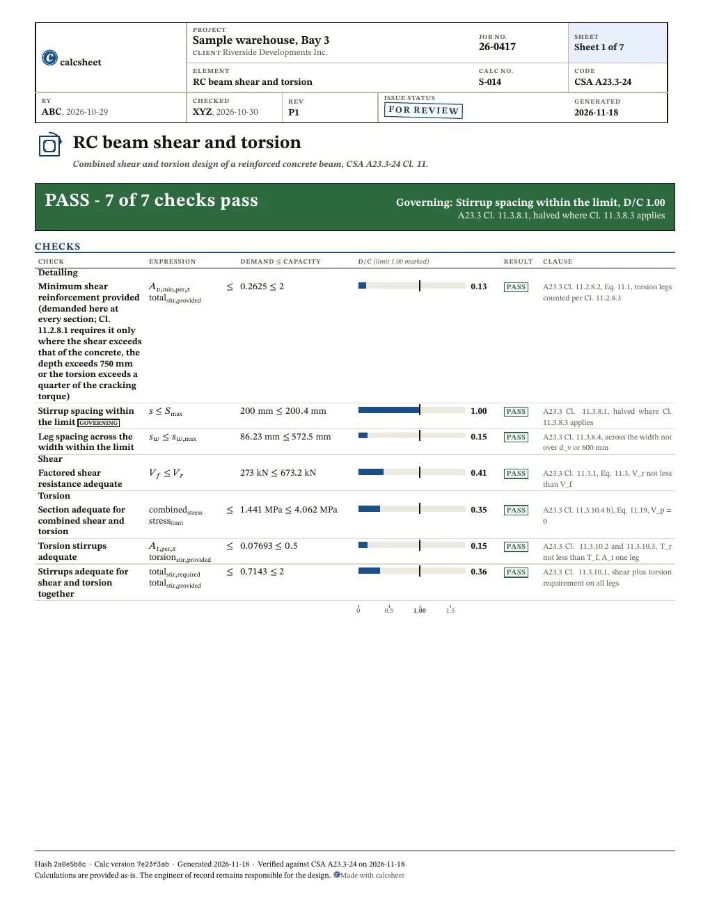
PASS Governing: Stirrup spacing within the limit, D/C 1.00, A23.3 Cl. 11.3.8.1, halved where Cl. 11.3.8.3 applies7 of 7 checks below pass

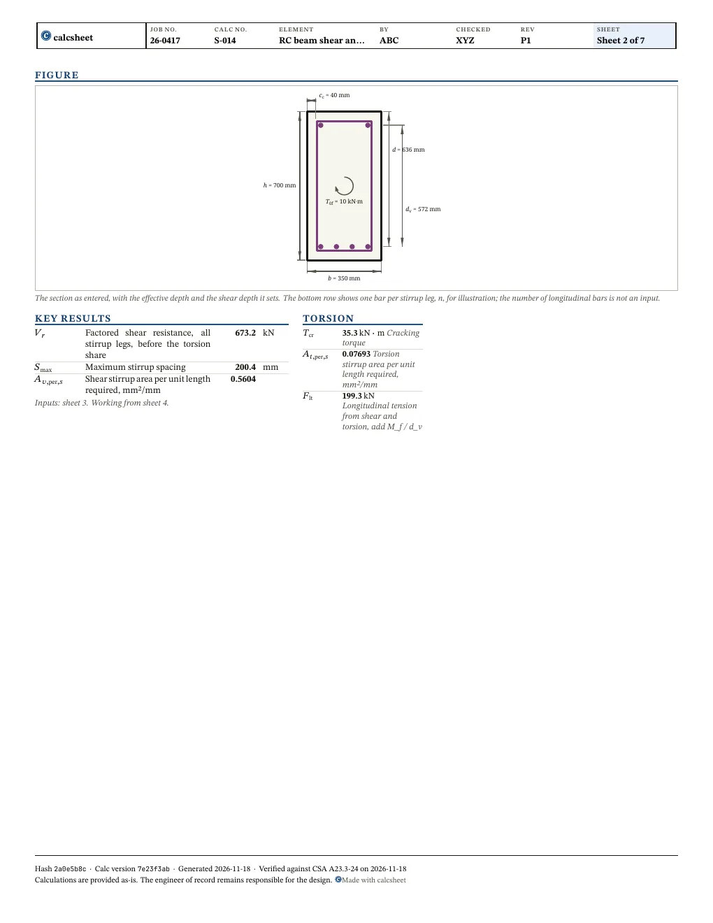
T0f = 10 kN·m b = 350 mm h = 700 mm d = 636 mm dv = 572 mm cc = 40 mm
The section as entered, with the effective depth and the shear depth it sets. The bottom row shows one bar per stirrup leg, n, for illustration; the number of longitudinal bars is not an input.

Given

Jump to results

Type any value, everything below recomputes. Hover or tap a symbol to trace it.

Loads
changed from the declared value VfV_{f} kN\mathrm{kN}0-20,000
changed from the declared value T0fT_{0f} kN⋅m\mathrm{kN} \cdot \mathrm{m}0-5,000
Section
changed from the declared value bb mm\mathrm{mm}300-2,000
changed from the declared value hh mm\mathrm{mm}350-3,000
changed from the declared value ccc_{c} mm\mathrm{mm}20-100
Materials
changed from the declared value fyf_{y} MPa\mathrm{MPa}200-500
changed from the declared value fygf_{\mathrm{yg}} MPa\mathrm{MPa}300-500
changed from the declared value fcf_{c} MPa\mathrm{MPa}15-60
changed from the declared value
Reinforcement
changed from the declared value
changed from the declared value nn 2-12
changed from the declared value ss mm\mathrm{mm}25-1,000

Title block

Optional. Printed in the title block of the PDF.

Checks

All 7 checks pass. Largest D/C 1.00, Stirrup spacing within the limit.

Show all 7 checks and 2 design conditions

! marks a check that passes with D/C at or above 0.95: close to its limit. The band is a site convention, not a code limit.

Detailing

Check D/C Utilisation Result
Minimum shear reinforcement provided (demanded here at every section; Cl. 11.2.8.1 requires it only where the shear exceeds that of the concrete, the depth exceeds 750 mm or the torsion exceeds a quarter of the cracking torque)A23.3 Cl. 11.2.8.2, Eq. 11.1, torsion legs counted per Cl. 11.2.8.3Av,min,per,s≤totalstir,provided⇒0.2625≤2\htmlClass{sym-A_v_min_per_s}{A_{v,\mathrm{min},\mathrm{per},s}} \leq \htmlClass{sym-total_stir_provided}{\mathrm{total}_{\mathrm{stir},\mathrm{provided}}} \quad \Rightarrow \quad \htmlClass{sym-A_v_min_per_s}{0.2625} \leq \htmlClass{sym-total_stir_provided}{2} 0.13 PASS
Stirrup spacing within the limitA23.3 Cl. 11.3.8.1, halved where Cl. 11.3.8.3 appliess≤Smax⇒200 mm≤200.4 mm\htmlClass{sym-s}{s} \leq \htmlClass{sym-S_max}{S_{\mathrm{max}}} \quad \Rightarrow \quad \htmlClass{sym-s}{200\ \mathrm{mm}} \leq \htmlClass{sym-S_max}{200.4\ \mathrm{mm}} 1.00 PASS
Leg spacing across the width within the limitA23.3 Cl. 11.3.8.4, across the width not over d_v or 600 mmsw≤sw,max⇒86.23 mm≤572.5 mm\htmlClass{sym-s_w}{s_{w}} \leq \htmlClass{sym-s_w_max}{s_{w,\mathrm{max}}} \quad \Rightarrow \quad \htmlClass{sym-s_w}{86.23\ \mathrm{mm}} \leq \htmlClass{sym-s_w_max}{572.5\ \mathrm{mm}} 0.15 PASS

Shear

Check D/C Utilisation Result
Factored shear resistance adequateA23.3 Cl. 11.3.1, Eq. 11.3, V_r not less than V_fVf≤Vr⇒273 kN≤673.2 kN\htmlClass{sym-V_f}{V_{f}} \leq \htmlClass{sym-V_r}{V_{r}} \quad \Rightarrow \quad \htmlClass{sym-V_f}{273\ \mathrm{kN}} \leq \htmlClass{sym-V_r}{673.2\ \mathrm{kN}} 0.41 PASS

Torsion

Check D/C Utilisation Result
Section adequate for combined shear and torsionA23.3 Cl. 11.3.10.4 b), Eq. 11.19, V_p = 0combinedstress≤stresslimit⇒1.441 MPa≤4.062 MPa\htmlClass{sym-combined_stress}{\mathrm{combined}_{\mathrm{stress}}} \leq \htmlClass{sym-stress_limit}{\mathrm{stress}_{\mathrm{limit}}} \quad \Rightarrow \quad \htmlClass{sym-combined_stress}{1.441\ \mathrm{MPa}} \leq \htmlClass{sym-stress_limit}{4.062\ \mathrm{MPa}} 0.35 PASS
Torsion stirrups adequateA23.3 Cl. 11.3.10.2 and 11.3.10.3, T_r not less than T_f, A_t one legAt,per,s≤torsionstir,provided⇒0.07693≤0.5\htmlClass{sym-A_t_per_s}{A_{t,\mathrm{per},s}} \leq \htmlClass{sym-torsion_stir_provided}{\mathrm{torsion}_{\mathrm{stir},\mathrm{provided}}} \quad \Rightarrow \quad \htmlClass{sym-A_t_per_s}{0.07693} \leq \htmlClass{sym-torsion_stir_provided}{0.5} 0.15 PASS
Stirrups adequate for shear and torsion togetherA23.3 Cl. 11.3.10.1, shear plus torsion requirement on all legstotalstir,required≤totalstir,provided⇒0.7143≤2\htmlClass{sym-total_stir_required}{\mathrm{total}_{\mathrm{stir},\mathrm{required}}} \leq \htmlClass{sym-total_stir_provided}{\mathrm{total}_{\mathrm{stir},\mathrm{provided}}} \quad \Rightarrow \quad \htmlClass{sym-total_stir_required}{0.7143} \leq \htmlClass{sym-total_stir_provided}{2} 0.36 PASS

Design conditions

Torsion reinforcement requiredA23.3 Cl. 11.2.9.1, torsion neglected unless T_f exceeds 0.25 T_crT0f>0.25⋅Tcr⇒10 kN⋅m>0.25⋅35.3 kN⋅m\htmlClass{sym-T_0f}{T_{0f}} > 0.25 \cdot \htmlClass{sym-T_cr}{T_{\mathrm{cr}}} \quad \Rightarrow \quad \htmlClass{sym-T_0f}{10\ \mathrm{kN} \cdot \mathrm{m}} > 0.25 \cdot \htmlClass{sym-T_cr}{35.3\ \mathrm{kN} \cdot \mathrm{m}}
Shear stress not over 0.125 lambda phi_c f'cA23.3 Cl. 11.3.8.3, V_f against 0.125 lambda phi_c f'c b_w d_v, V_p = 0shearstress≤threshold⇒1.362 MPa≤2.031 MPa\htmlClass{sym-shear_stress}{\mathrm{shear}_{\mathrm{stress}}} \leq \htmlClass{sym-threshold}{\mathrm{threshold}} \quad \Rightarrow \quad \htmlClass{sym-shear_stress}{1.362\ \mathrm{MPa}} \leq \htmlClass{sym-threshold}{2.031\ \mathrm{MPa}}

Results

Shear

Quantity Description Value Unit
Vr\htmlClass{sym-V_r}{V_{r}} Factored shear resistance, all stirrup legs, before the torsion share 673.2 kN\mathrm{kN}
Smax\htmlClass{sym-S_max}{S_{\mathrm{max}}} Maximum stirrup spacing 200.4 mm\mathrm{mm}
Av,per,s\htmlClass{sym-A_v_per_s}{A_{v,\mathrm{per},s}} Shear stirrup area per unit length required, mm²/mm 0.5604

Torsion

Quantity Description Value Unit
Tcr\htmlClass{sym-T_cr}{T_{\mathrm{cr}}} Cracking torque 35.3 kN⋅m\mathrm{kN} \cdot \mathrm{m}
At,per,s\htmlClass{sym-A_t_per_s}{A_{t,\mathrm{per},s}} Torsion stirrup area per unit length required, mm²/mm 0.07693
Flt\htmlClass{sym-F_lt}{F_{\mathrm{lt}}} Longitudinal tension from shear and torsion, add M_f / d_v 199.3 kN\mathrm{kN}
Also worth checking
  • Longitudinal reinforcement for shear and torsion: the tension force is reported, not checked against the flexural steel (Cl. 11.3.9 and 11.3.10.6)
  • Shear near a support: the factored shear and torsion are taken as given, without the design section of Cl. 11.3.2
  • Members in significant axial tension, outside the simplified method of Cl. 11.3.6.3
  • Prestressed members: the shear carried by prestressing is taken as zero
  • Redistribution of compatibility torsion (Cl. 11.2.9.2)
  • Box sections: crushing is checked by the solid-section Eq. 11.19, not Eq. 11.18 of Cl. 11.3.10.4 a)
  • Torsion detailing of Cl. 11.2.7: 135 degree hooks on closed stirrups and a corner bar of diameter at least s/16
  • Clear distance between stirrup legs and between stirrups, A23.1 Cl. 6.6.5.2 (at least 1.4 bar diameters, 1.4 times the nominal maximum coarse aggregate size and 30 mm), and whether the stirrup size can be bent as a closed stirrup with 135 degree hooks, are not checked
  • Specified strengths under 20 MPa are outside Cl. 8.6.1.1 and allowed only for mass concrete, plain concrete or evaluation of existing structures, Cl. 8.6.1.3; the input accepts 15 MPa and up
  • Regions near supports, concentrated loads or openings, where plane sections do not hold, need a strut-and-tie model, Cl. 11.1.2
  • Anchorage of the shear stirrups, Cl. 11.2.5 and 12.13
  • Cut-off of longitudinal bars in a tension zone: the 15 percent cut in V_r and the 0.35 d_v spacing, Cl. 11.2.13
  • Hanger reinforcement where a load acts on the side face of the beam, Cl. 11.2.12
  • Shear in one direction only; biaxial shear, Cl. 11.3.11, is not checked
  • Beta from Eq. 11.9 assumes a nominal maximum coarse aggregate size of at least 20 mm, Cl. 11.3.6.3 b)

Derivation

1.1Concrete density factor
λ=1(Normal (λ = 1.00) | CSA A23.3 Cl. 8.6.5)\begin{aligned} \htmlClass{sym-lamb}{\lambda} &= 1 \quad \left(\text{Normal (λ = 1.00) | CSA A23.3 Cl. 8.6.5}\right) \end{aligned}
1.2Resistance factor, concrete
ϕc=0.65(Resistance factor, concrete | CSA A23.3 Cl. 8.4.2)\begin{aligned} \htmlClass{sym-phi_c}{\phi_{c}} &= 0.65 \quad \left(\text{Resistance factor, concrete | CSA A23.3 Cl. 8.4.2}\right) \end{aligned}
1.3Resistance factor, reinforcement
ϕs=0.85(Resistance factor, reinforcing bars | CSA A23.3 Cl. 8.4.3 a))\begin{aligned} \htmlClass{sym-phi_s}{\phi_{s}} &= 0.85 \quad \left(\text{Resistance factor, reinforcing bars | CSA A23.3 Cl. 8.4.3 a)}\right) \end{aligned}
1.4Stirrup diameter
ds=11.3 mm(Stirrup diameter | 10M)\begin{aligned} \htmlClass{sym-d_s}{d_{s}} &= 11.3\ \mathrm{mm} \quad \left(\text{Stirrup diameter | 10M}\right) \end{aligned}
1.5Longitudinal bar diameter
db=25.2 mm(Longitudinal bar diameter | 25M)\begin{aligned} \htmlClass{sym-d_b}{d_{b}} &= 25.2\ \mathrm{mm} \quad \left(\text{Longitudinal bar diameter | 25M}\right) \end{aligned}
1.6Stirrup leg area
Asb=100 mm2(Area of one stirrup leg | 10M)\begin{aligned} \htmlClass{sym-A_sb}{A_{\mathrm{sb}}} &= 100\ \mathrm{mm}^{2} \quad \left(\text{Area of one stirrup leg | 10M}\right) \end{aligned}
2.1Compression strut angle

A23.3 Cl. 11.3.6.3, simplified method

θ=radians⁡(35)=radians⁡(35)=0.6109\begin{aligned} \htmlClass{sym-theta}{\theta} &= \operatorname{radians}\left(35\right) \\ &= \operatorname{radians}\left(35\right) \\ &= 0.6109 \end{aligned}
2.2Effective depth
d=h−cc−ds−db2=700 mm−40 mm−11.3 mm−25.2 mm2=636.1 mm\begin{aligned} \htmlClass{sym-d}{d} &= \htmlClass{sym-h}{h} - \htmlClass{sym-c_c}{c_{c}} - \htmlClass{sym-d_s}{d_{s}} - \frac{\htmlClass{sym-d_b}{d_{b}}}{2} \\ &= \htmlClass{sym-h}{700\ \mathrm{mm}} - \htmlClass{sym-c_c}{40\ \mathrm{mm}} - \htmlClass{sym-d_s}{11.3\ \mathrm{mm}} - \frac{\htmlClass{sym-d_b}{25.2\ \mathrm{mm}}}{2} \\ &= 636.1\ \mathrm{mm} \end{aligned}
2.3Effective shear depth

A23.3 Cl. 3.2, effective shear depth

dv=max⁡(0.9⋅d,0.72⋅h)=max⁡(0.9⋅636.1 mm,0.72⋅700 mm)=572.5 mm\begin{aligned} \htmlClass{sym-d_v}{d_{v}} &= \max\left(0.9 \cdot \htmlClass{sym-d}{d}, 0.72 \cdot \htmlClass{sym-h}{h}\right) \\ &= \max\left(0.9 \cdot \htmlClass{sym-d}{636.1\ \mathrm{mm}}, 0.72 \cdot \htmlClass{sym-h}{700\ \mathrm{mm}}\right) \\ &= 572.5\ \mathrm{mm} \end{aligned}
2.4Stirrup centreline width
x0=b−2⋅cc−ds=350 mm−2⋅40 mm−11.3 mm=258.7 mm\begin{aligned} \htmlClass{sym-x_0}{x_{0}} &= \htmlClass{sym-b}{b} - 2 \cdot \htmlClass{sym-c_c}{c_{c}} - \htmlClass{sym-d_s}{d_{s}} \\ &= \htmlClass{sym-b}{350\ \mathrm{mm}} - 2 \cdot \htmlClass{sym-c_c}{40\ \mathrm{mm}} - \htmlClass{sym-d_s}{11.3\ \mathrm{mm}} \\ &= 258.7\ \mathrm{mm} \end{aligned}
2.5Stirrup centreline depth
y0=h−2⋅cc−ds=700 mm−2⋅40 mm−11.3 mm=608.7 mm\begin{aligned} \htmlClass{sym-y_0}{y_{0}} &= \htmlClass{sym-h}{h} - 2 \cdot \htmlClass{sym-c_c}{c_{c}} - \htmlClass{sym-d_s}{d_{s}} \\ &= \htmlClass{sym-h}{700\ \mathrm{mm}} - 2 \cdot \htmlClass{sym-c_c}{40\ \mathrm{mm}} - \htmlClass{sym-d_s}{11.3\ \mathrm{mm}} \\ &= 608.7\ \mathrm{mm} \end{aligned}
2.6Perimeter of the stirrup centreline

A23.3 Cl. 3.2, p_h

Ph=2⋅(x0+y0)=2⋅(258.7 mm+608.7 mm)=1735 mm\begin{aligned} \htmlClass{sym-P_h}{P_{h}} &= 2 \cdot \left(\htmlClass{sym-x_0}{x_{0}} + \htmlClass{sym-y_0}{y_{0}}\right) \\ &= 2 \cdot \left(\htmlClass{sym-x_0}{258.7\ \mathrm{mm}} + \htmlClass{sym-y_0}{608.7\ \mathrm{mm}}\right) \\ &= 1735\ \mathrm{mm} \end{aligned}
2.7Area inside the stirrup centreline

A23.3 Cl. 3.2, A_oh

A0h=x0⋅y0=258.7 mm⋅608.7 mm=157471 mm2\begin{aligned} \htmlClass{sym-A_0h}{A_{0h}} &= \htmlClass{sym-x_0}{x_{0}} \cdot \htmlClass{sym-y_0}{y_{0}} \\ &= \htmlClass{sym-x_0}{258.7\ \mathrm{mm}} \cdot \htmlClass{sym-y_0}{608.7\ \mathrm{mm}} \\ &= 157471\ \mathrm{mm}^{2} \end{aligned}
2.8Cotangent of the strut angle
cotθ=1tan⁡(θ)=1tan⁡(0.6109)=1.428\begin{aligned} \htmlClass{sym-cot_theta}{\mathrm{cot}_{\theta}} &= \frac{1}{\tan\left(\htmlClass{sym-theta}{\theta}\right)} \\ &= \frac{1}{\tan\left(\htmlClass{sym-theta}{0.6109}\right)} \\ &= 1.428 \end{aligned}
3.1Minimum stirrup area per spacing

A23.3 Cl. 11.2.8.2, Eq. 11.1

Av,min,per,s=0.06⋅fc⋅1 MPa⋅bfy⋅1 mm=0.06⋅25 MPa⋅1 MPa⋅350 mm400 MPa⋅1 mm=0.2625\begin{aligned} \htmlClass{sym-A_v_min_per_s}{A_{v,\mathrm{min},\mathrm{per},s}} &= \frac{0.06 \cdot \sqrt{\htmlClass{sym-f_c}{f_{c}} \cdot 1\ \mathrm{MPa}} \cdot \htmlClass{sym-b}{b}}{\htmlClass{sym-f_y}{f_{y}} \cdot 1\ \mathrm{mm}} \\ &= \frac{0.06 \cdot \sqrt{\htmlClass{sym-f_c}{25\ \mathrm{MPa}} \cdot 1\ \mathrm{MPa}} \cdot \htmlClass{sym-b}{350\ \mathrm{mm}}}{\htmlClass{sym-f_y}{400\ \mathrm{MPa}} \cdot 1\ \mathrm{mm}} \\ &= 0.2625 \end{aligned}
3.2Stirrup area provided per spacing
totalstir,provided=n⋅Asbs⋅1 mm=4⋅100 mm2200 mm⋅1 mm=2\begin{aligned} \htmlClass{sym-total_stir_provided}{\mathrm{total}_{\mathrm{stir},\mathrm{provided}}} &= \frac{\htmlClass{sym-n}{n} \cdot \htmlClass{sym-A_sb}{A_{\mathrm{sb}}}}{\htmlClass{sym-s}{s} \cdot 1\ \mathrm{mm}} \\ &= \frac{\htmlClass{sym-n}{4} \cdot \htmlClass{sym-A_sb}{100\ \mathrm{mm}^{2}}}{\htmlClass{sym-s}{200\ \mathrm{mm}} \cdot 1\ \mathrm{mm}} \\ &= 2 \end{aligned}

totalstir,provided≤11⋅Av,min,per,s⇒2≤11⋅0.2625\mathrm{total}_{\mathrm{stir},\mathrm{provided}} \leq 11 \cdot A_{v,\mathrm{min},\mathrm{per},s} \quad \Rightarrow \quad 2 \leq 11 \cdot 0.2625

4.1Effective web width

A23.3 Cl. 11.2.10.1, minimum web width within d

bw=b=350 mm\begin{aligned} \htmlClass{sym-b_w}{b_{w}} &= \htmlClass{sym-b}{b} \\ &= 350\ \mathrm{mm} \end{aligned}

Av,min,per,s≤totalstir,provided⇒0.2625≤2A_{v,\mathrm{min},\mathrm{per},s} \leq \mathrm{total}_{\mathrm{stir},\mathrm{provided}} \quad \Rightarrow \quad 0.2625 \leq 2

fyg≤400 MPa⇒400 MPa≤400 MPaf_{\mathrm{yg}} \leq 400\ \mathrm{MPa} \quad \Rightarrow \quad 400\ \mathrm{MPa} \leq 400\ \mathrm{MPa}

4.2Concrete shear factor
β=0.18(At least the minimum stirrups, f_yg up to 400 MPa | Cl. 11.3.6.3 a))\begin{aligned} \htmlClass{sym-beta}{\beta} &= 0.18 \quad \left(\text{At least the minimum stirrups, f\_yg up to 400 MPa | Cl. 11.3.6.3 a)}\right) \end{aligned}
4.3Concrete shear resistance

A23.3 Cl. 11.3.4, Eq. 11.6

Vc=ϕc⋅λ⋅β⋅fc⋅1 MPa⋅bw⋅dv=0.65⋅1⋅0.18⋅25 MPa⋅1 MPa⋅350 mm⋅572.5 mm=117.2 kN\begin{aligned} \htmlClass{sym-V_c}{V_{c}} &= \htmlClass{sym-phi_c}{\phi_{c}} \cdot \htmlClass{sym-lamb}{\lambda} \cdot \htmlClass{sym-beta}{\beta} \cdot \sqrt{\htmlClass{sym-f_c}{f_{c}} \cdot 1\ \mathrm{MPa}} \cdot \htmlClass{sym-b_w}{b_{w}} \cdot \htmlClass{sym-d_v}{d_{v}} \\ &= \htmlClass{sym-phi_c}{0.65} \cdot \htmlClass{sym-lamb}{1} \cdot \htmlClass{sym-beta}{0.18} \cdot \sqrt{\htmlClass{sym-f_c}{25\ \mathrm{MPa}} \cdot 1\ \mathrm{MPa}} \cdot \htmlClass{sym-b_w}{350\ \mathrm{mm}} \cdot \htmlClass{sym-d_v}{572.5\ \mathrm{mm}} \\ &= 117.2\ \mathrm{kN} \end{aligned}
4.4Stirrup area
Av=n⋅Asb=4⋅100 mm2=400 mm2\begin{aligned} \htmlClass{sym-A_v}{A_{v}} &= \htmlClass{sym-n}{n} \cdot \htmlClass{sym-A_sb}{A_{\mathrm{sb}}} \\ &= \htmlClass{sym-n}{4} \cdot \htmlClass{sym-A_sb}{100\ \mathrm{mm}^{2}} \\ &= 400\ \mathrm{mm}^{2} \end{aligned}
4.5Stirrup shear resistance

A23.3 Cl. 11.3.5.1, Eq. 11.7

Vs=ϕs⋅Av⋅fy⋅dv⋅cotθs=0.85⋅400 mm2⋅400 MPa⋅572.5 mm⋅1.428200 mm=556 kN\begin{aligned} \htmlClass{sym-V_s}{V_{s}} &= \frac{\htmlClass{sym-phi_s}{\phi_{s}} \cdot \htmlClass{sym-A_v}{A_{v}} \cdot \htmlClass{sym-f_y}{f_{y}} \cdot \htmlClass{sym-d_v}{d_{v}} \cdot \htmlClass{sym-cot_theta}{\mathrm{cot}_{\theta}}}{\htmlClass{sym-s}{s}} \\ &= \frac{\htmlClass{sym-phi_s}{0.85} \cdot \htmlClass{sym-A_v}{400\ \mathrm{mm}^{2}} \cdot \htmlClass{sym-f_y}{400\ \mathrm{MPa}} \cdot \htmlClass{sym-d_v}{572.5\ \mathrm{mm}} \cdot \htmlClass{sym-cot_theta}{1.428}}{\htmlClass{sym-s}{200\ \mathrm{mm}}} \\ &= 556\ \mathrm{kN} \end{aligned}
4.6Maximum shear resistance

A23.3 Cl. 11.3.3, Eq. 11.5

Vrmax=0.25⋅ϕc⋅fc⋅bw⋅dv=0.25⋅0.65⋅25 MPa⋅350 mm⋅572.5 mm=814 kN\begin{aligned} \htmlClass{sym-V_rmax}{V_{\mathrm{rmax}}} &= 0.25 \cdot \htmlClass{sym-phi_c}{\phi_{c}} \cdot \htmlClass{sym-f_c}{f_{c}} \cdot \htmlClass{sym-b_w}{b_{w}} \cdot \htmlClass{sym-d_v}{d_{v}} \\ &= 0.25 \cdot \htmlClass{sym-phi_c}{0.65} \cdot \htmlClass{sym-f_c}{25\ \mathrm{MPa}} \cdot \htmlClass{sym-b_w}{350\ \mathrm{mm}} \cdot \htmlClass{sym-d_v}{572.5\ \mathrm{mm}} \\ &= 814\ \mathrm{kN} \end{aligned}
4.7Shear resistance, all stirrup legs

A23.3 Cl. 11.3.3, Eqs. 11.4 and 11.5

Vr=min⁡(Vc+Vs,Vrmax)=min⁡(117.2 kN+556 kN,814 kN)=673.2 kN\begin{aligned} \htmlClass{sym-V_r}{V_{r}} &= \min\left(\htmlClass{sym-V_c}{V_{c}} + \htmlClass{sym-V_s}{V_{s}}, \htmlClass{sym-V_rmax}{V_{\mathrm{rmax}}}\right) \\ &= \min\left(\htmlClass{sym-V_c}{117.2\ \mathrm{kN}} + \htmlClass{sym-V_s}{556\ \mathrm{kN}}, \htmlClass{sym-V_rmax}{814\ \mathrm{kN}}\right) \\ &= 673.2\ \mathrm{kN} \end{aligned}
shearutilization=VfVr=273 kN673.2 kN=0.4055\begin{aligned} \htmlClass{sym-shear_utilization}{\mathrm{shear}_{\mathrm{utilization}}} &= \frac{\htmlClass{sym-V_f}{V_{f}}}{\htmlClass{sym-V_r}{V_{r}}} \\ &= \frac{\htmlClass{sym-V_f}{273\ \mathrm{kN}}}{\htmlClass{sym-V_r}{673.2\ \mathrm{kN}}} \\ &= 0.4055 \end{aligned}
5.1Gross area

A23.3 Cl. 3.2, A_c

Ac=b⋅h=350 mm⋅700 mm=245000 mm2\begin{aligned} \htmlClass{sym-A_c}{A_{c}} &= \htmlClass{sym-b}{b} \cdot \htmlClass{sym-h}{h} \\ &= \htmlClass{sym-b}{350\ \mathrm{mm}} \cdot \htmlClass{sym-h}{700\ \mathrm{mm}} \\ &= 245000\ \mathrm{mm}^{2} \end{aligned}
5.2Outside perimeter

A23.3 Cl. 3.2, p_c

Pc=2⋅(b+h)=2⋅(350 mm+700 mm)=2100 mm\begin{aligned} \htmlClass{sym-P_c}{P_{c}} &= 2 \cdot \left(\htmlClass{sym-b}{b} + \htmlClass{sym-h}{h}\right) \\ &= 2 \cdot \left(\htmlClass{sym-b}{350\ \mathrm{mm}} + \htmlClass{sym-h}{700\ \mathrm{mm}}\right) \\ &= 2100\ \mathrm{mm} \end{aligned}
5.3Cracking torque

A23.3 Cl. 11.2.9.1, Eq. 11.2

Tcr=0.38⋅Ac2⋅λ⋅ϕc⋅fc⋅1 MPaPc=0.38⋅(245000 mm2)2⋅1⋅0.65⋅25 MPa⋅1 MPa2100 mm=35.3 kN⋅m\begin{aligned} \htmlClass{sym-T_cr}{T_{\mathrm{cr}}} &= \frac{0.38 \cdot \htmlClass{sym-A_c}{A_{c}}^{2} \cdot \htmlClass{sym-lamb}{\lambda} \cdot \htmlClass{sym-phi_c}{\phi_{c}} \cdot \sqrt{\htmlClass{sym-f_c}{f_{c}} \cdot 1\ \mathrm{MPa}}}{\htmlClass{sym-P_c}{P_{c}}} \\ &= \frac{0.38 \cdot \left(\htmlClass{sym-A_c}{245000\ \mathrm{mm}^{2}}\right)^{2} \cdot \htmlClass{sym-lamb}{1} \cdot \htmlClass{sym-phi_c}{0.65} \cdot \sqrt{\htmlClass{sym-f_c}{25\ \mathrm{MPa}} \cdot 1\ \mathrm{MPa}}}{\htmlClass{sym-P_c}{2100\ \mathrm{mm}}} \\ &= 35.3\ \mathrm{kN} \cdot \mathrm{m} \end{aligned}

Torsion reinforcement required, A23.3 Cl. 11.2.9.1, torsion neglected unless T_f exceeds 0.25 T_cr. T0f>0.25⋅Tcr⇒10 kN⋅m>0.25⋅35.3 kN⋅mT_{0f} > 0.25 \cdot T_{\mathrm{cr}} \quad \Rightarrow \quad 10\ \mathrm{kN} \cdot \mathrm{m} > 0.25 \cdot 35.3\ \mathrm{kN} \cdot \mathrm{m}

6.1Shear stirrups required per spacing

A23.3 Cl. 11.3.3 and 11.3.5.1, Eqs. 11.4 and 11.7

Av,per,s=max⁡(Vf−Vcϕs⋅fy⋅dv⋅cotθ⋅1 mm,0)=max⁡(273 kN−117.2 kN0.85⋅400 MPa⋅572.5 mm⋅1.428⋅1 mm,0)=0.5604\begin{aligned} \htmlClass{sym-A_v_per_s}{A_{v,\mathrm{per},s}} &= \max\left(\frac{\htmlClass{sym-V_f}{V_{f}} - \htmlClass{sym-V_c}{V_{c}}}{\htmlClass{sym-phi_s}{\phi_{s}} \cdot \htmlClass{sym-f_y}{f_{y}} \cdot \htmlClass{sym-d_v}{d_{v}} \cdot \htmlClass{sym-cot_theta}{\mathrm{cot}_{\theta}} \cdot 1\ \mathrm{mm}}, 0\right) \\ &= \max\left(\frac{\htmlClass{sym-V_f}{273\ \mathrm{kN}} - \htmlClass{sym-V_c}{117.2\ \mathrm{kN}}}{\htmlClass{sym-phi_s}{0.85} \cdot \htmlClass{sym-f_y}{400\ \mathrm{MPa}} \cdot \htmlClass{sym-d_v}{572.5\ \mathrm{mm}} \cdot \htmlClass{sym-cot_theta}{1.428} \cdot 1\ \mathrm{mm}}, 0\right) \\ &= 0.5604 \end{aligned}
6.2Area enclosed by the shear flow

A23.3 Cl. 11.3.10.3

A0=0.85⋅A0h=0.85⋅157471 mm2=133850 mm2\begin{aligned} \htmlClass{sym-A_0}{A_{0}} &= 0.85 \cdot \htmlClass{sym-A_0h}{A_{0h}} \\ &= 0.85 \cdot \htmlClass{sym-A_0h}{157471\ \mathrm{mm}^{2}} \\ &= 133850\ \mathrm{mm}^{2} \end{aligned}
6.3Torsion stirrups required per spacing, one leg

A23.3 Cl. 11.3.10.3, Eq. 11.17

At,per,s=T0f2⋅A0⋅ϕs⋅fy⋅cotθ⋅1 mm=10 kN⋅m2⋅133850 mm2⋅0.85⋅400 MPa⋅1.428⋅1 mm=0.07693\begin{aligned} \htmlClass{sym-A_t_per_s}{A_{t,\mathrm{per},s}} &= \frac{\htmlClass{sym-T_0f}{T_{0f}}}{2 \cdot \htmlClass{sym-A_0}{A_{0}} \cdot \htmlClass{sym-phi_s}{\phi_{s}} \cdot \htmlClass{sym-f_y}{f_{y}} \cdot \htmlClass{sym-cot_theta}{\mathrm{cot}_{\theta}} \cdot 1\ \mathrm{mm}} \\ &= \frac{\htmlClass{sym-T_0f}{10\ \mathrm{kN} \cdot \mathrm{m}}}{2 \cdot \htmlClass{sym-A_0}{133850\ \mathrm{mm}^{2}} \cdot \htmlClass{sym-phi_s}{0.85} \cdot \htmlClass{sym-f_y}{400\ \mathrm{MPa}} \cdot \htmlClass{sym-cot_theta}{1.428} \cdot 1\ \mathrm{mm}} \\ &= 0.07693 \end{aligned}
6.4Torsion stirrups provided per spacing, one leg
torsionstir,provided=Asbs⋅1 mm=100 mm2200 mm⋅1 mm=0.5\begin{aligned} \htmlClass{sym-torsion_stir_provided}{\mathrm{torsion}_{\mathrm{stir},\mathrm{provided}}} &= \frac{\htmlClass{sym-A_sb}{A_{\mathrm{sb}}}}{\htmlClass{sym-s}{s} \cdot 1\ \mathrm{mm}} \\ &= \frac{\htmlClass{sym-A_sb}{100\ \mathrm{mm}^{2}}}{\htmlClass{sym-s}{200\ \mathrm{mm}} \cdot 1\ \mathrm{mm}} \\ &= 0.5 \end{aligned}
torsionstir,utilization=At,per,storsionstir,provided=0.076930.5=0.1539\begin{aligned} \htmlClass{sym-torsion_stir_utilization}{\mathrm{torsion}_{\mathrm{stir},\mathrm{utilization}}} &= \frac{\htmlClass{sym-A_t_per_s}{A_{t,\mathrm{per},s}}}{\htmlClass{sym-torsion_stir_provided}{\mathrm{torsion}_{\mathrm{stir},\mathrm{provided}}}} \\ &= \frac{\htmlClass{sym-A_t_per_s}{0.07693}}{\htmlClass{sym-torsion_stir_provided}{0.5}} \\ &= 0.1539 \end{aligned}
6.5Stirrups required per spacing

A23.3 Cl. 11.3.10.1

totalstir,required=Av,per,s+2⋅At,per,s=0.5604+2⋅0.07693=0.7143\begin{aligned} \htmlClass{sym-total_stir_required}{\mathrm{total}_{\mathrm{stir},\mathrm{required}}} &= \htmlClass{sym-A_v_per_s}{A_{v,\mathrm{per},s}} + 2 \cdot \htmlClass{sym-A_t_per_s}{A_{t,\mathrm{per},s}} \\ &= \htmlClass{sym-A_v_per_s}{0.5604} + 2 \cdot \htmlClass{sym-A_t_per_s}{0.07693} \\ &= 0.7143 \end{aligned}
totalstir,utilization=totalstir,requiredtotalstir,provided=0.71432=0.3571\begin{aligned} \htmlClass{sym-total_stir_utilization}{\mathrm{total}_{\mathrm{stir},\mathrm{utilization}}} &= \frac{\htmlClass{sym-total_stir_required}{\mathrm{total}_{\mathrm{stir},\mathrm{required}}}}{\htmlClass{sym-total_stir_provided}{\mathrm{total}_{\mathrm{stir},\mathrm{provided}}}} \\ &= \frac{\htmlClass{sym-total_stir_required}{0.7143}}{\htmlClass{sym-total_stir_provided}{2}} \\ &= 0.3571 \end{aligned}
7.1Shear stress
shearstress=Vfbw⋅dv=273 kN350 mm⋅572.5 mm=1.362 MPa\begin{aligned} \htmlClass{sym-shear_stress}{\mathrm{shear}_{\mathrm{stress}}} &= \frac{\htmlClass{sym-V_f}{V_{f}}}{\htmlClass{sym-b_w}{b_{w}} \cdot \htmlClass{sym-d_v}{d_{v}}} \\ &= \frac{\htmlClass{sym-V_f}{273\ \mathrm{kN}}}{\htmlClass{sym-b_w}{350\ \mathrm{mm}} \cdot \htmlClass{sym-d_v}{572.5\ \mathrm{mm}}} \\ &= 1.362\ \mathrm{MPa} \end{aligned}
7.2Spacing threshold stress

A23.3 Cl. 11.3.8.3, as a stress on b_w d_v

threshold=0.125⋅ϕc⋅λ⋅fc=0.125⋅0.65⋅1⋅25 MPa=2.031 MPa\begin{aligned} \htmlClass{sym-threshold}{\mathrm{threshold}} &= 0.125 \cdot \htmlClass{sym-phi_c}{\phi_{c}} \cdot \htmlClass{sym-lamb}{\lambda} \cdot \htmlClass{sym-f_c}{f_{c}} \\ &= 0.125 \cdot \htmlClass{sym-phi_c}{0.65} \cdot \htmlClass{sym-lamb}{1} \cdot \htmlClass{sym-f_c}{25\ \mathrm{MPa}} \\ &= 2.031\ \mathrm{MPa} \end{aligned}

Shear stress not over 0.125 lambda phi_c f'c, A23.3 Cl. 11.3.8.3, V_f against 0.125 lambda phi_c f'c b_w d_v, V_p = 0. shearstress≤threshold⇒1.362 MPa≤2.031 MPa\mathrm{shear}_{\mathrm{stress}} \leq \mathrm{threshold} \quad \Rightarrow \quad 1.362\ \mathrm{MPa} \leq 2.031\ \mathrm{MPa}

7.3Maximum stirrup spacing

A23.3 Cl. 11.3.8.3, half of Cl. 11.3.8.1

Smax=min⁡(300 mm,0.35⋅dv)=min⁡(300 mm,0.35⋅572.5 mm)=200.4 mm\begin{aligned} \htmlClass{sym-S_max}{S_{\mathrm{max}}} &= \min\left(300\ \mathrm{mm}, 0.35 \cdot \htmlClass{sym-d_v}{d_{v}}\right) \\ &= \min\left(300\ \mathrm{mm}, 0.35 \cdot \htmlClass{sym-d_v}{572.5\ \mathrm{mm}}\right) \\ &= 200.4\ \mathrm{mm} \end{aligned}
7.4Leg spacing across the width
sw=x0n−1=258.7 mm4−1=86.23 mm\begin{aligned} \htmlClass{sym-s_w}{s_{w}} &= \frac{\htmlClass{sym-x_0}{x_{0}}}{\htmlClass{sym-n}{n} - 1} \\ &= \frac{\htmlClass{sym-x_0}{258.7\ \mathrm{mm}}}{\htmlClass{sym-n}{4} - 1} \\ &= 86.23\ \mathrm{mm} \end{aligned}
7.5Maximum leg spacing across the width

A23.3 Cl. 11.3.8.4

sw,max=min⁡(dv,600 mm)=min⁡(572.5 mm,600 mm)=572.5 mm\begin{aligned} \htmlClass{sym-s_w_max}{s_{w,\mathrm{max}}} &= \min\left(\htmlClass{sym-d_v}{d_{v}}, 600\ \mathrm{mm}\right) \\ &= \min\left(\htmlClass{sym-d_v}{572.5\ \mathrm{mm}}, 600\ \mathrm{mm}\right) \\ &= 572.5\ \mathrm{mm} \end{aligned}
8.1Web curvature factor for torsion

A23.3 Cl. 11.3.10.4

αT=1−0.005⋅fc1 MPa=1−0.005⋅25 MPa1 MPa=0.875\begin{aligned} \htmlClass{sym-alpha_T}{\alpha_{T}} &= 1 - \frac{0.005 \cdot \htmlClass{sym-f_c}{f_{c}}}{1\ \mathrm{MPa}} \\ &= 1 - \frac{0.005 \cdot \htmlClass{sym-f_c}{25\ \mathrm{MPa}}}{1\ \mathrm{MPa}} \\ &= 0.875 \end{aligned}
8.2Torsion stress

A23.3 Cl. 11.3.10.4 b), torsion term

torsionstress=T0f⋅Pc0.85⋅αT⋅Ac2=10 kN⋅m⋅2100 mm0.85⋅0.875⋅(245000 mm2)2=0.4704 MPa\begin{aligned} \htmlClass{sym-torsion_stress}{\mathrm{torsion}_{\mathrm{stress}}} &= \frac{\htmlClass{sym-T_0f}{T_{0f}} \cdot \htmlClass{sym-P_c}{P_{c}}}{0.85 \cdot \htmlClass{sym-alpha_T}{\alpha_{T}} \cdot \htmlClass{sym-A_c}{A_{c}}^{2}} \\ &= \frac{\htmlClass{sym-T_0f}{10\ \mathrm{kN} \cdot \mathrm{m}} \cdot \htmlClass{sym-P_c}{2100\ \mathrm{mm}}}{0.85 \cdot \htmlClass{sym-alpha_T}{0.875} \cdot \left(\htmlClass{sym-A_c}{245000\ \mathrm{mm}^{2}}\right)^{2}} \\ &= 0.4704\ \mathrm{MPa} \end{aligned}
8.3Combined shear and torsion stress

A23.3 Cl. 11.3.10.4 b)

combinedstress=shearstress2+torsionstress2=(1.362 MPa)2+(0.4704 MPa)2=1.441 MPa\begin{aligned} \htmlClass{sym-combined_stress}{\mathrm{combined}_{\mathrm{stress}}} &= \sqrt{\htmlClass{sym-shear_stress}{\mathrm{shear}_{\mathrm{stress}}}^{2} + \htmlClass{sym-torsion_stress}{\mathrm{torsion}_{\mathrm{stress}}}^{2}} \\ &= \sqrt{\left(\htmlClass{sym-shear_stress}{1.362\ \mathrm{MPa}}\right)^{2} + \left(\htmlClass{sym-torsion_stress}{0.4704\ \mathrm{MPa}}\right)^{2}} \\ &= 1.441\ \mathrm{MPa} \end{aligned}
8.4Crushing stress limit

A23.3 Cl. 11.3.10.4 b)

stresslimit=0.25⋅ϕc⋅fc=0.25⋅0.65⋅25 MPa=4.062 MPa\begin{aligned} \htmlClass{sym-stress_limit}{\mathrm{stress}_{\mathrm{limit}}} &= 0.25 \cdot \htmlClass{sym-phi_c}{\phi_{c}} \cdot \htmlClass{sym-f_c}{f_{c}} \\ &= 0.25 \cdot \htmlClass{sym-phi_c}{0.65} \cdot \htmlClass{sym-f_c}{25\ \mathrm{MPa}} \\ &= 4.062\ \mathrm{MPa} \end{aligned}
torsionsection,utilization=combinedstressstresslimit=1.441 MPa4.062 MPa=0.3548\begin{aligned} \htmlClass{sym-torsion_section_utilization}{\mathrm{torsion}_{\mathrm{section},\mathrm{utilization}}} &= \frac{\htmlClass{sym-combined_stress}{\mathrm{combined}_{\mathrm{stress}}}}{\htmlClass{sym-stress_limit}{\mathrm{stress}_{\mathrm{limit}}}} \\ &= \frac{\htmlClass{sym-combined_stress}{1.441\ \mathrm{MPa}}}{\htmlClass{sym-stress_limit}{4.062\ \mathrm{MPa}}} \\ &= 0.3548 \end{aligned}
9.1Stirrups available for shear per spacing

A23.3 Cl. 11.3.10.1, shear share

Avs,per,s=max⁡(totalstir,provided−2⋅At,per,s,0)=max⁡(2−2⋅0.07693,0)=1.846\begin{aligned} \htmlClass{sym-A_vs_per_s}{A_{\mathrm{vs},\mathrm{per},s}} &= \max\left(\htmlClass{sym-total_stir_provided}{\mathrm{total}_{\mathrm{stir},\mathrm{provided}}} - 2 \cdot \htmlClass{sym-A_t_per_s}{A_{t,\mathrm{per},s}}, 0\right) \\ &= \max\left(\htmlClass{sym-total_stir_provided}{2} - 2 \cdot \htmlClass{sym-A_t_per_s}{0.07693}, 0\right) \\ &= 1.846 \end{aligned}
9.2Stirrup shear for tension

A23.3 Cl. 11.3.5.1, Eq. 11.7

Vs,shear=ϕs⋅Avs,per,s⋅1 mm⋅fy⋅dv⋅cotθ=0.85⋅1.846⋅1 mm⋅400 MPa⋅572.5 mm⋅1.428=513.2 kN\begin{aligned} \htmlClass{sym-V_s_shear}{V_{s,\mathrm{shear}}} &= \htmlClass{sym-phi_s}{\phi_{s}} \cdot \htmlClass{sym-A_vs_per_s}{A_{\mathrm{vs},\mathrm{per},s}} \cdot 1\ \mathrm{mm} \cdot \htmlClass{sym-f_y}{f_{y}} \cdot \htmlClass{sym-d_v}{d_{v}} \cdot \htmlClass{sym-cot_theta}{\mathrm{cot}_{\theta}} \\ &= \htmlClass{sym-phi_s}{0.85} \cdot \htmlClass{sym-A_vs_per_s}{1.846} \cdot 1\ \mathrm{mm} \cdot \htmlClass{sym-f_y}{400\ \mathrm{MPa}} \cdot \htmlClass{sym-d_v}{572.5\ \mathrm{mm}} \cdot \htmlClass{sym-cot_theta}{1.428} \\ &= 513.2\ \mathrm{kN} \end{aligned}
9.3Stirrup shear, capped at V_f

A23.3 Cl. 11.3.9.2, V_s not over V_f

Vs,lt=min⁡(Vs,shear,Vf)=min⁡(513.2 kN,273 kN)=273 kN\begin{aligned} \htmlClass{sym-V_s_lt}{V_{s,\mathrm{lt}}} &= \min\left(\htmlClass{sym-V_s_shear}{V_{s,\mathrm{shear}}}, \htmlClass{sym-V_f}{V_{f}}\right) \\ &= \min\left(\htmlClass{sym-V_s_shear}{513.2\ \mathrm{kN}}, \htmlClass{sym-V_f}{273\ \mathrm{kN}}\right) \\ &= 273\ \mathrm{kN} \end{aligned}
9.4Shear term

A23.3 Cl. 11.3.10.6, V_p = 0

shearterm=Vf−0.5⋅Vs,lt=273 kN−0.5⋅273 kN=136.5 kN\begin{aligned} \htmlClass{sym-shear_term}{\mathrm{shear}_{\mathrm{term}}} &= \htmlClass{sym-V_f}{V_{f}} - 0.5 \cdot \htmlClass{sym-V_s_lt}{V_{s,\mathrm{lt}}} \\ &= \htmlClass{sym-V_f}{273\ \mathrm{kN}} - 0.5 \cdot \htmlClass{sym-V_s_lt}{273\ \mathrm{kN}} \\ &= 136.5\ \mathrm{kN} \end{aligned}
9.5Torsion term

A23.3 Cl. 11.3.10.6

torsionterm=0.45⋅Ph⋅T0f2⋅A0=0.45⋅1735 mm⋅10 kN⋅m2⋅133850 mm2=29.16 kN\begin{aligned} \htmlClass{sym-torsion_term}{\mathrm{torsion}_{\mathrm{term}}} &= \frac{0.45 \cdot \htmlClass{sym-P_h}{P_{h}} \cdot \htmlClass{sym-T_0f}{T_{0f}}}{2 \cdot \htmlClass{sym-A_0}{A_{0}}} \\ &= \frac{0.45 \cdot \htmlClass{sym-P_h}{1735\ \mathrm{mm}} \cdot \htmlClass{sym-T_0f}{10\ \mathrm{kN} \cdot \mathrm{m}}}{2 \cdot \htmlClass{sym-A_0}{133850\ \mathrm{mm}^{2}}} \\ &= 29.16\ \mathrm{kN} \end{aligned}
9.6Longitudinal tension

A23.3 Eq. 11.14 with Cl. 11.3.10.6

Flt=shearterm2+torsionterm2⋅cotθ=(136.5 kN)2+(29.16 kN)2⋅1.428=199.3 kN\begin{aligned} \htmlClass{sym-F_lt}{F_{\mathrm{lt}}} &= \sqrt{\htmlClass{sym-shear_term}{\mathrm{shear}_{\mathrm{term}}}^{2} + \htmlClass{sym-torsion_term}{\mathrm{torsion}_{\mathrm{term}}}^{2}} \cdot \htmlClass{sym-cot_theta}{\mathrm{cot}_{\theta}} \\ &= \sqrt{\left(\htmlClass{sym-shear_term}{136.5\ \mathrm{kN}}\right)^{2} + \left(\htmlClass{sym-torsion_term}{29.16\ \mathrm{kN}}\right)^{2}} \cdot \htmlClass{sym-cot_theta}{1.428} \\ &= 199.3\ \mathrm{kN} \end{aligned}

Report

Sheet 1 and the first sheet of the working of the PDF report, at the declared values with a sample title block. Pro.

Show the two sheets
Sheet 1 of the RC beam shear and torsion report: title block, verdict, checks and figures
Sheet 1: title block, verdict, checks, figures · full size
The first sheet of the working in the RC beam shear and torsion report: each step with its clause
The working: each step with its clause · full size

Questions

When does Cl. 11.2.9.1 require torsion reinforcement?

When the factored torsion exceeds a quarter of the cracking torque, T_0f > 0.25 T_cr, per Cl. 11.2.9.1. Below that the torsion may be neglected. This sheet still sizes A_t/s either way, which errs on the safe side.

Why is the stirrup demand A_v/s + 2 A_t/s?

Cl. 11.3.10.1 adds the transverse steel for shear to that for torsion. Torsion is resisted by a shear flow around the closed perimeter, so A_t/s is needed in each leg on that perimeter and both side legs carry it, hence the 2. Shear uses every leg crossing the crack, so the combined demand is compared with all n legs, while the torsion check on its own counts one outside leg.

What sets S_max, the maximum stirrup spacing?

Cl. 11.3.8.1 limits it to the lesser of 600 mm and 0.7 d_v. Cl. 11.3.8.3 halves that when the shear stress exceeds 0.125 lambda phi_c f'c or the torsion exceeds 0.25 T_cr.

Why is theta fixed at 35 degrees, and how is beta chosen?

The sheet uses the simplified method of Cl. 11.3.6.3, which fixes theta at 35 degrees and holds to f'c of 60 MPa. With at least the minimum stirrups of Eq. 11.1, beta is 0.18 for f_yg, the specified yield strength of the longitudinal bars, up to 400 MPa and 0.4 / (1 + f_yg / 320) above it. With less, beta comes from Eq. 11.9, which the clause gives for no transverse reinforcement and assumes coarse aggregate of at least 20 mm; it is taken here for stirrups below the minimum, which the clause does not cover, and with d_v under about 280 mm (300 mm above 400 MPa) it gives a beta above Cl. 11.3.6.3 a). The minimum stirrup check fails in that case. The stirrups take f_y and the longitudinal bars f_yg.

Revision history

chore(examples,docs): audit the four concrete calcs PR #304 changed
ValueWasNowUnit
f_yg400MPa\mathrm{MPa}