Checks
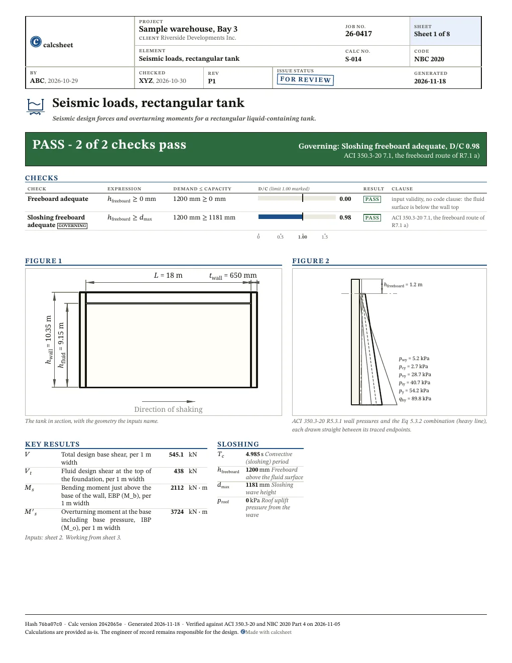
All 2 checks pass. Largest D/C 0.98, Sloshing freeboard adequate.
Show all 2 checks
! marks a check that passes with D/C at or above 0.95: close to its limit. The band is a site convention, not a code limit.
| Check |
D/C |
Utilisation |
Result |
| Freeboard adequateinput validity, no code clause: the fluid surface is below the wall top |
0.00 |
|
✓ PASS |
| Sloshing freeboard adequateACI 350.3-20 7.1, the freeboard route of R7.1 a) |
0.98 |
|
! PASS |
Wall pressures in kPa at height y above the base, per metre of wall width: q_hy, p_iy, p_cy, p_wy, p_vy and p_y, which is Eq 5.3.2 at each height. Leading is q_hy + p_y and trailing is q_hy - p_y, the two wall cases of R5.3.1.
| y, m | Hydrostatic | Impulsive | Convective | Wall | Vertical | Combined | Leading | Trailing |
| 0.0 | 89.8 | 40.7 | 2.7 | 5.2 | 28.7 | 54.2 | 144.0 | 35.5 |
| 0.9 | 80.8 | 37.2 | 3.3 | 5.2 | 25.9 | 49.8 | 130.6 | 31.0 |
| 1.8 | 71.8 | 33.8 | 3.8 | 5.2 | 23.0 | 45.4 | 117.2 | 26.4 |
| 2.7 | 62.8 | 30.3 | 4.4 | 5.2 | 20.1 | 41.0 | 103.8 | 21.8 |
| 3.7 | 53.9 | 26.8 | 5.0 | 5.2 | 17.2 | 36.6 | 90.5 | 17.2 |
| 4.6 | 44.9 | 23.3 | 5.5 | 5.2 | 14.4 | 32.4 | 77.2 | 12.5 |
| 5.5 | 35.9 | 19.8 | 6.1 | 5.2 | 11.5 | 28.2 | 64.1 | 7.8 |
| 6.4 | 26.9 | 16.3 | 6.7 | 5.2 | 8.6 | 24.1 | 51.0 | 2.8 |
| 7.3 | 18.0 | 12.8 | 7.3 | 5.2 | 5.7 | 20.2 | 38.2 | -2.3 |
| 8.2 | 9.0 | 9.3 | 7.8 | 5.2 | 2.9 | 16.7 | 25.7 | -7.7 |
| 9.2 | 0.0 | 5.8 | 8.4 | 5.2 | 0.0 | 13.8 | 13.8 | -13.8 |
| 10.3 | 0.0 | 0.0 | 0.0 | 5.2 | 0.0 | 5.2 | 5.2 | -5.2 |
Also worth checking
- The strength of the walls, base slab and roof against the forces and pressures, which this sheet only produces
- The dynamic earth pressure on a buried wall, which R5.3.2 leaves to the geotechnical engineer
- The confined sloshing mass that R7.1 adds to the impulsive mass, and corner sloshing from both directions
- Sliding, overturning and bearing of the tank on its foundation
- I, R_i and R_c are inputs from ACI 350.3-20 Tables 4.1.1a and 4.1.1b; NBC's I_E, R_d and R_o are not applied, and any freeboard rule of the owner
- Shear transfer at the wall-to-floor, wall-to-wall and wall-to-roof joints, Cl. 3.3.2 and 5.2.1
- The in-plane forces on the walls parallel to the shaking, Cl. 5.3.1
- The 80 percent floor of Cl. 9.5 on the Cl. 9.4 values, and the deterministic cap of Cl. 4.2.1
- Other liquid levels, including the tank or a cell empty, R1.1
- P_eg and h_eg, which are inputs to be taken from Chapter 8 or the geotechnical report
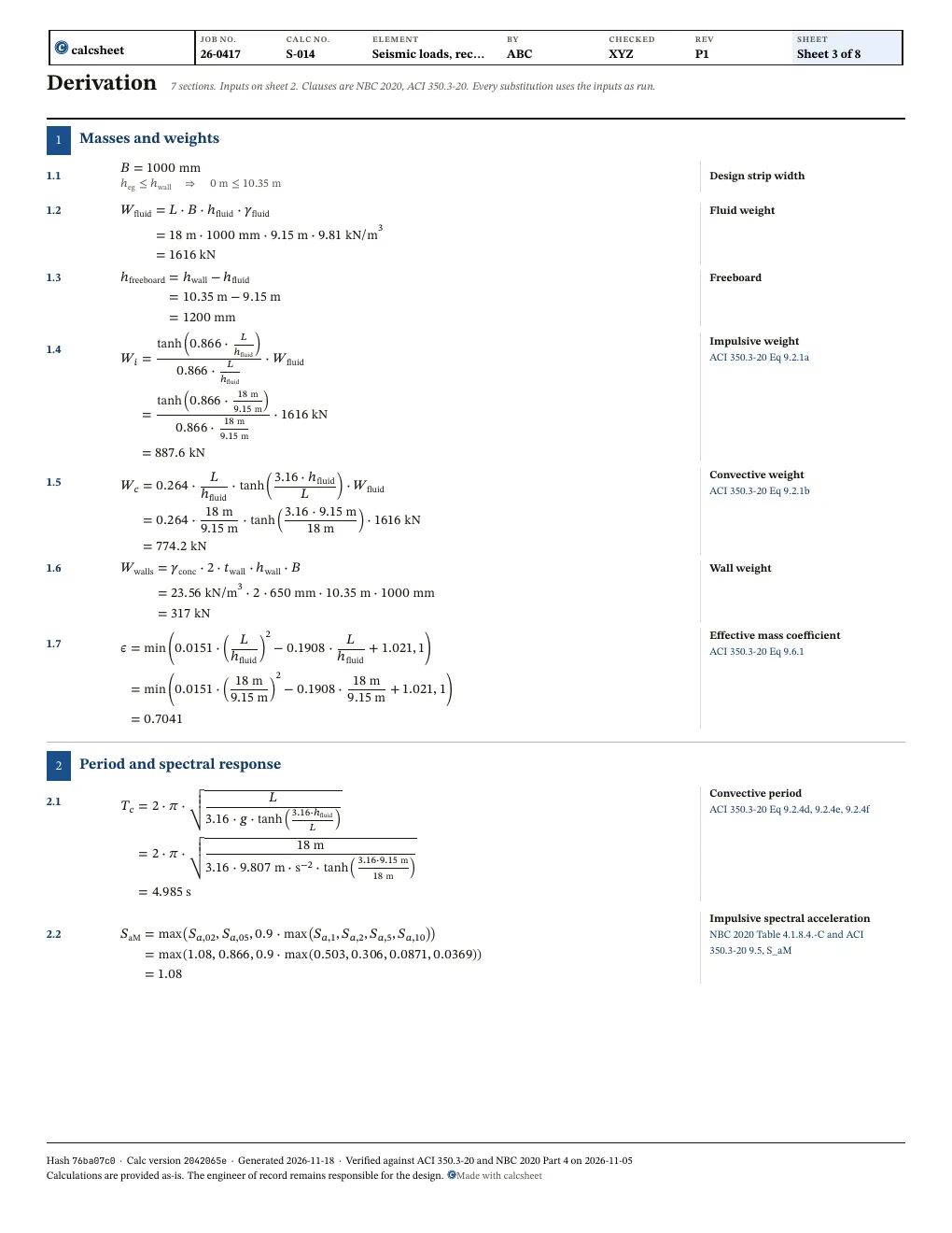
Derivation
and
7.7Convective distribution origin
Questions
How do the NBCC 2020 values S_a_02 to S_a_10 replace S_s, S_1, F_a and F_v, and what does the sheet assume?
ACI 350.3-20 reads the ASCE 7-16 maps, its site coefficients and a long-period corner T_L, and Canada has none of them. NBCC 2020 publishes the 5% damped Sa(T) at 2% in 50 years for the site designation itself, with the site coefficients already inside, so the sheet takes Sa at 0.2, 0.5, 1.0, 2.0, 5.0 and 10 s from the Earthquakes Canada seismic hazard tool and goes through ACI 350.3-20 Section 9.5, the route written for a site-specific spectrum, whose probabilistic spectrum in 4.2.2 is that one. S_aM is the greater of Sa(0.2) and Sa(0.5), the plateau of NBC Table 4.1.8.4.-C, and not below 90% of the largest longer-period value: the impulsive plateau, since the impulsive mode is taken as rigid (Appendix A step 8) and T_i is not computed. S_cM is 1.5 times Sa at the sloshing period T_c, the factor for the 0.5% damping of that mode, read log-log between the NBCC periods and held at the 10 s value beyond 10 s, which is conservative since Table 4.1.8.4.-C ends there. Then C_i = 2/3 S_aM, C_c = 2/3 S_cM and C_t = C_i (Eq 9.5a, 9.5b, 9.4.3b). Not applied: the 80% floor of 9.5, which needs the ASCE 7 values of 9.4, and the deterministic cap of 4.2.1, which can only lower the spectrum. The defaults are Vancouver, site class C, from the tool; check them against the tool for your site and designation. Why the 2/3 stays is the next question.
Why does the sheet keep ACI's 2/3 of Eq 9.5a and its I and R_wi on NBCC values?
Because ACI 350.3-20 4.2.2 defines its probabilistic spectrum as the 5% damped one with 2% in 50 years, which is what NBCC publishes, and Eq 9.5a to 9.5c apply the 2/3 to it. The 2/3 is a fixed margin and not a risk target: the 2003 NEHRP commentary sets the design ground motion at 1/1.5 of the maximum considered one for the collapse margin of structures designed to the provisions, first on these same 2% in 50 year maps, and ASCE kept it when it moved to risk-targeted values. ACI says its force levels and R factors give strength-level results like the IBC, so I from Table 4.1.1a (1.0 for risk categories I and II, 1.25 for III, 1.5 for IV) and R_wi from Table 4.1.1b (2.25 for a fixed or hinged base on grade, with R_wc 1.0 for every type) were set against the 2/3 spectrum. Keeping the 2/3 and those factors puts a tank at the demand of an ASCE 7 tank at the same hazard: NBCC Victoria Sa(0.2) is 1.30 g against Seattle S_MS of 1.365 g (Tremblay et al., 2016), so the two spectra are close. Dropping the 2/3 and keeping them would make the tank 1.5 times that; at the Vancouver defaults V goes from 545 to 818 kN and d_max from 1.18 to 1.77 m against 1.2 m of freeboard. NBCC's I_E and R_d R_o are not applied on top, which would count the importance and the ductility twice. Not settled: ACI 350.3 does not name NBCC, NBC 2020 Commentary J puts free-standing tanks outside the code and asks for ground motion consistent with it, and no Canadian source found says whether to apply the 2/3. NBC takes its margin through R_d R_o, treats the 2% in 50 year spectrum as its design level, and so loads buildings more heavily than ASCE 7. One Canadian paper (J.L. Richards, CCEE) used the NBC spectrum with no 2/3 and I_E, R_d and R_o of 1 for an elastic check of existing tanks, without discussing the factor. Confirm the choice with the owner, pick the risk category from the consequence of failure and R_wi for the base condition; the sheet looks neither up. P_c is divided by R_wc, so the default leaves the convective force unreduced.
How do I use p_iy, p_cy, p_wy and p_vy on a wall?
Not by adding them. ACI 350.3 Eq 5.3.2 combines them at each height by the square root of the sum of squares, (p_iy + p_wy), p_cy and p_vy, which is p_y; the table lists it at every height, and p_y_base and p_y_top are its two ends. Apply p_y on top of the hydrostatic q_hy: it adds on the leading wall and reduces the load on the trailing one, so design both, as the last two columns give. p_cy is linear over the whole depth while h_c is below two thirds of it and starts at the height y_cy0 above that, as R5.3.1 gives. None of it includes the dynamic earth pressure, which R5.3.2 leaves to the geotechnical engineer, and none of it enters V or M_s, which come from P_c and the other forces. Every force and pressure is per metre of tank width, since B is a unit 1 m.
What does the sloshing_freeboard_adequate check cover, and what does it leave out?
It compares h_freeboard with d_max of Eq 7.1a, (L/2) C_c I, the code's method. d_max_refined is Housner's Eq 7.1b, which the code allows in lieu of 7.1a; the commentary says 7.1a is 10 to 20% greater than the exact results, but 7.1b is only 4% lower at the defaults and can be the larger at small L / h_fluid, so read it beside d_max and do not take it as the lower bound. It has no solution once C_c reaches 0.633 / tanh(3.16 h_fluid / L), and then it repeats Eq 7.1a. ACI 350.3 does not fix a freeboard: where overtopping is tolerable it asks for none, and otherwise for freeboard, a roof designed for the uplift, or a spillway. On a covered tank whose freeboard is below d_max / I, p_roof is the R7.1 uplift pressure, C_LF gamma_fluid (d_max / I - h_o), on the length L_i of roof at each end wall. The commentary leaves C_LF to the engineer between 1.4 and 3.2, and 2.2 is its compromise. Left out: the confined sloshing mass that R7.1 adds to the impulsive mass, the corner sloshing it raises by SRSS of both directions, which needs the tank's other dimension, and any freeboard rule of the owner.
 calcsheet
 Seismic loads, rectangular tank